“To choose the right Inductor, it is necessary to fully understand the performance of the inductor and how the desired internal circuit performance is related to the information in the supplier’s data sheet. This article explains the inductor catalog and important specifications of inductors for experienced power conversion experts and non-professionals.
“
To choose the right inductor, it is necessary to fully understand the performance of the inductor and how the desired internal circuit performance is related to the information in the supplier’s data sheet. This article explains the inductor catalog and important specifications of inductors for experienced power conversion experts and non-professionals.

introduce
The use of DC-DC converters is becoming more and more common. As electronic systems have become smaller, more mobile, more complex, and more popular, power requirements have become diversified. The available battery voltage, required operating voltage, size and shape requirements are constantly changing, which makes equipment designers need to constantly find new ways to solve the power conversion problem. Product requirements often need to be met by improving performance and reducing size, so optimization becomes very important. For power conversion, not all applications can be “one-size-fits-all”. For example, many practical applications require the use of thin components like Figure 1.

Figure 1: Designing a thin and light converter requires the use of thin inductors

In addition to the growing market for bulk purchases of converters, many circuit designers now also design their own DC-DC conversion circuits instead of relying on power supply companies, so more circuit designers can choose their own components. The basic DC-DC conversion circuit is a very mature technology and is still developing slowly. Therefore, professional authors can write practical auxiliary design materials, and equipment designers can use these materials to design their own converters. Some easily available software can also simplify the process of these designs1.
After determining the circuit topology, one of the key design tasks is to select components. Many circuit design programs can list the required component parameter values. At this time, the designer should start by determining the required inductance value, and finally select a component from the available range to perform the work. The inductors used in DC-DC converters come in various shapes and sizes. Figures 2 and 3 show two of them. In order to compare different types and select the appropriate components for a specific application, designers must correctly understand the published specifications for these inductors.

Figure 2: E-shaped iron core inductor wound with flat wire

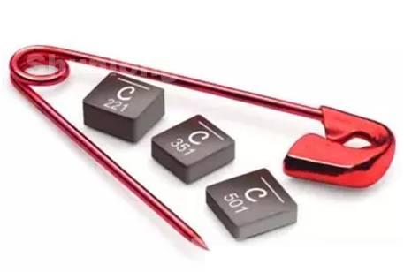
Figure 3: Magnetically shielded molded inductor with rugged structure for high-density circuits

DC-DC converter requirements
In short, the function of the DC-DC converter is to provide a stable DC output voltage under a given input voltage. To adjust the DC output voltage without exceeding a given load current range and/or input voltage range, a converter is usually required. Ideally, the DC output is “pure”, that is, the ripple current or ripple voltage is controlled within a specified level. In addition, the process of transferring power from the power source to the load must also achieve a specified efficiency level. To achieve these goals, the selection of power inductors is an important step.
Power inductor parameters
Inductance performance can be explained by several numbers. Table 1 is a typical inductance data sheet. These data describe a surface mount power inductor used in a DC-DC converter.
Table 1: Excerpt from the catalog of typical inductors 2 

a. The inductance value is measured at 1MHz and 0.1Vrms
b. Isat is the typical value when the inductance value drops by 30%
c. Irms is the typical value when causing a temperature rise of 40℃
d. All parameters are measured at 25℃
definition
L―Inductance value: The main functional parameters of the inductor, calculated by the converter design formula, are used to determine the ability of the inductor to handle output power and control ripple current.
DCR-DC resistance: The resistance of the component depends on the length and diameter of the winding copper wire used.
SRF-self-resonant frequency: the frequency point at which the inductance value of the inductor coil resonates with its distributed capacitance.
Isat―Saturation current: The current that causes the iron core to saturate when passing through the inductor, causing the inductance value to drop.
Irms-Root Mean Square Current: The current that continuously passes through the inductor and causes the maximum allowable temperature rise.
To use the ratings correctly, you must understand how they are derived. Since the data sheet cannot show the performance under all working conditions, it is necessary to understand how the ratings change under different working conditions.
Inductance value (L)
The inductance value is the main parameter to realize the required circuit function, and it is also the first parameter to be calculated in most design processes. This value is calculated based on the standard of providing a certain minimum energy storage capacity (or volt-microsecond capacity) and reducing the output current ripple. If the inductance value used is smaller than the calculated result, the AC ripple of the DC output will be increased. Using inductance values that are too large or too small may force the converter to change between continuous and discontinuous operating modes.
tolerance
Most applications of DC-DC converters do not have particularly strict requirements for inductance tolerances. For most components, choosing standard tolerance products is cost-effective and can meet the requirements of most converters. The inductance tolerance of Table 1 is ±20%, which is suitable for most converters.
Test Conditions
■ Voltage. The rated inductance value should indicate the frequency and test voltage used. Most catalog rated inductance values are based on “small” sinusoidal voltages. For inductor suppliers, this is the easiest to implement and the most convenient method for repeated applications, and is suitable for deriving inductance values for most applications.
■ Waveform. Sinusoidal voltage is a standard instrument test condition, usually it can well ensure that the obtained inductance value matches the inductance value calculated by the design formula.
■ Test frequency. Most power inductors do not change much within the range of 20kHz to 500kHz, so the commonly used and more appropriate approach is to use a rating based on 100kHz. It must be remembered that as the frequency increases, the inductance value will eventually decrease. The reason for this phenomenon may come from the frequency roll-off characteristics of the iron core material used, or it may come from the resonance of the coil inductance and its distributed capacitance. Since most converters work in the range of 50kHz to 500kHz, 100kHz is a suitable standard test frequency. When the switching frequency increases to 500kHz, 1MHz and above, it is even more important to consider the use of rated values based on the actual application frequency.
resistance
DC resistance (DCR)
DCR is only a measure of the copper wire used in the inductor, strictly based on the diameter and length of the copper wire. The value specified in the catalog is usually the “maximum value”, but a nominal value with tolerance can also be specified. The second method may be more instructive by giving the nominal value or expected resistance, but at the same time it may unnecessarily tighten the specifications, because the resistance of the product is too small and there is always no harm.
Like the resistivity of coil materials that are usually copper, DCR also changes with temperature. The DCR rating should consider the environmental test temperature, which is very important. The temperature coefficient of resistance of copper is approximately +0.4% per degree Celsius3. Therefore, the product shown with a maximum rating of 0.009 ohms has a corresponding maximum rating of 0.011 ohms at 85°C, which is only 2 milliohms away, but the total change is 25%. The relationship between expected DCR and temperature is shown in Figure 4.
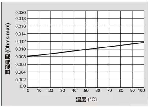
Figure 4: Based on the expected DC resistance of 0.009Ω Max at 25°C

AC resistance
This parameter is generally not indicated in the inductance data sheet, and it is usually not a problem to be considered unless the AC component of the operating frequency or current is greater than the DC component.
Due to the skin effect, the resistance of most inductance coils increases as the operating frequency increases. If the AC or ripple current is small relative to the average or DC current, then DCR is a good measure of resistance loss. The skin effect varies with the copper wire diameter and frequency3. Therefore, to include this data, the complete frequency curve of each inductor listed in the catalog needs to be given.

Figure 5: AC resistance/DC resistance of American wire gauge 22 round copper wire

This is unnecessary for most applications below 500kHz. It can be seen from Figure 5 that at frequencies below about 200kHz, AC resistance cannot be compared with DC resistance. Even above this frequency, if the AC current is not greater than the DC component, the AC resistance does not pose a problem. However, if the frequency is higher than 200-300kHz, the recommended approach is to ask the supplier for information on the relationship between loss and frequency as a supplement to the published information.
If you want to minimize the size of components, designers should choose components with as large resistance as possible. Under normal circumstances, reducing DCR means that thicker copper wires must be used, and the overall size may be larger. Therefore, optimizing DCR selection is a trade-off between power efficiency, component allowable voltage drop, and component size.
To choose the right inductor, it is necessary to fully understand the performance of the inductor and how the desired internal circuit performance is related to the information in the supplier’s data sheet. This article explains the inductor catalog and important specifications of inductors for experienced power conversion experts and non-professionals.
introduce
The use of DC-DC converters is becoming more and more common. As electronic systems have become smaller, more mobile, more complex, and more popular, power requirements have become diversified. The available battery voltage, required operating voltage, size and shape requirements are constantly changing, which makes equipment designers need to constantly find new ways to solve the power conversion problem. Product requirements often need to be met by improving performance and reducing size, so optimization becomes very important. For power conversion, not all applications can be “one-size-fits-all”. For example, many practical applications require the use of thin components like Figure 1.
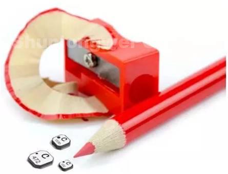
Figure 1: Designing a thin and light converter requires the use of thin inductors
In addition to the growing market for bulk purchases of converters, many circuit designers now also design their own DC-DC conversion circuits instead of relying on power supply companies, so more circuit designers can choose their own components. The basic DC-DC conversion circuit is a very mature technology and is still developing slowly. Therefore, professional authors can write practical auxiliary design materials, and equipment designers can use these materials to design their own converters. Some easily available software can also simplify the process of these designs1.
After determining the circuit topology, one of the key design tasks is to select components. Many circuit design programs can list the required component parameter values. At this time, the designer should start by determining the required inductance value, and finally select a component from the available range to perform the work. The inductors used in DC-DC converters come in various shapes and sizes. Figures 2 and 3 show two of them. In order to compare different types and select the appropriate components for a specific application, designers must correctly understand the published specifications for these inductors.
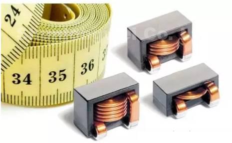
Figure 2: E-shaped iron core inductor wound with flat wire

Figure 3: Magnetically shielded molded inductor with rugged structure for high-density circuits
DC-DC converter requirements
In short, the function of the DC-DC converter is to provide a stable DC output voltage under a given input voltage. To adjust the DC output voltage without exceeding a given load current range and/or input voltage range, a converter is usually required. Ideally, the DC output is “pure”, that is, the ripple current or ripple voltage is controlled within a specified level. In addition, the process of transferring power from the power source to the load must also achieve a specified level of efficiency. To achieve these goals, the selection of power inductors is an important step.
Power inductor parameters
Inductance performance can be explained by several numbers. Table 1 is a typical inductance data sheet. These data describe a surface mount power inductor used in a DC-DC converter.
Table 1: Excerpt from the catalog of typical inductors 2 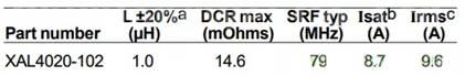
a. The inductance value is measured at 1MHz and 0.1Vrms
b. Isat is the typical value when the inductance value drops by 30%
c. Irms is the typical value when causing a temperature rise of 40℃
d. All parameters are measured at 25℃
definition
L―Inductance value: The main functional parameters of the inductor, calculated by the converter design formula, are used to determine the ability of the inductor to handle output power and control ripple current.
DCR-DC resistance: The resistance of the component depends on the length and diameter of the winding copper wire used.
SRF-self-resonant frequency: the frequency point at which the inductance value of the inductor coil resonates with its distributed capacitance.
Isat―Saturation current: The current that causes the iron core to saturate when passing through the inductor, causing the inductance value to drop.
Irms-Root Mean Square Current: The current that continuously passes through the inductor and causes the maximum allowable temperature rise.
To use the ratings correctly, you must understand how they are derived. Since the data sheet cannot show the performance under all working conditions, it is necessary to understand how the ratings change under different working conditions.
Inductance value (L)
The inductance value is the main parameter to realize the required circuit function, and it is also the first parameter to be calculated in most design processes. This value is calculated based on the standard of providing a certain minimum energy storage capacity (or volt-microsecond capacity) and reducing the output current ripple. If the inductance value used is smaller than the calculated result, the AC ripple of the DC output will be increased. Using too large or too small an inductance value may force the converter to change between continuous and discontinuous operating modes.
tolerance
Most applications of DC-DC converters do not have particularly strict requirements for inductance tolerances. For most components, choosing standard tolerance products is cost-effective and can meet the requirements of most converters. The inductance tolerance of Table 1 is ±20%, which is suitable for most converters.
Test Conditions
■ Voltage. The rated inductance value should indicate the frequency and test voltage used. Most catalog rated inductance values are based on “small” sinusoidal voltages. For inductor suppliers, this is the easiest to implement and the most convenient method for repeated applications, and is suitable for deriving inductance values for most applications.
■ Waveform. Sinusoidal voltage is a standard instrument test condition, usually it can well ensure that the obtained inductance value matches the inductance value calculated by the design formula.
■ Test frequency. Most power inductors do not change much within the range of 20kHz to 500kHz, so the commonly used and more appropriate approach is to use a rating based on 100kHz. It must be remembered that as the frequency increases, the inductance value will eventually decrease. The reason for this phenomenon may come from the frequency roll-off characteristics of the iron core material used, or it may come from the resonance of the coil inductance and its distributed capacitance. Since most converters work in the range of 50kHz to 500kHz, 100kHz is a suitable standard test frequency. When the switching frequency increases to 500kHz, 1MHz and above, it is even more important to consider the use of rated values based on the actual application frequency.
resistance
DC resistance (DCR)
DCR is only a measure of the copper wire used in the inductor, strictly based on the diameter and length of the copper wire. The value specified in the catalog is usually the “maximum value”, but a nominal value with tolerance can also be specified. The second method may be more instructive by giving the nominal value or expected resistance, but at the same time it may tighten the specifications unnecessarily, because the resistance of the product is too small and there is no harm.
Like the resistivity of coil materials that are usually copper, DCR also changes with temperature. The DCR rating should consider the environmental test temperature, which is very important. The temperature coefficient of resistance of copper is approximately +0.4% per degree Celsius3. Therefore, the product shown with a maximum rating of 0.009 ohms has a corresponding maximum rating of 0.011 ohms at 85°C, which is only 2 milliohms away, but the total change is 25%. The relationship between expected DCR and temperature is shown in Figure 4.

Figure 4: Based on the expected DC resistance of 0.009Ω Max at 25°C
AC resistance
This parameter is generally not indicated in the inductance data sheet, and it is usually not a problem to be considered unless the AC component of the operating frequency or current is greater than the DC component.
Due to the skin effect, the resistance of most inductance coils increases as the operating frequency increases. If the AC or ripple current is small relative to the average or DC current, then DCR is a good measure of resistance loss. The skin effect varies with the copper wire diameter and frequency3. Therefore, to include this data, the complete frequency curve of each inductor listed in the catalog needs to be given.
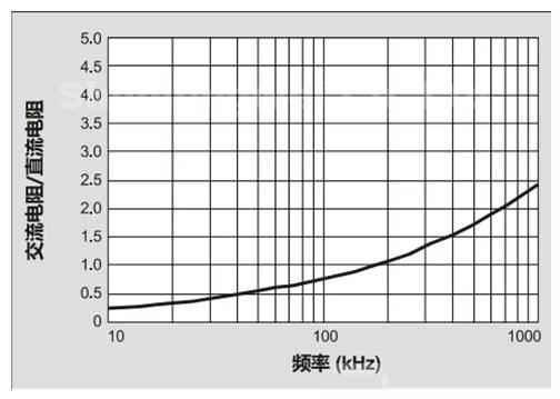
Figure 5: AC resistance/DC resistance of American wire gauge 22 round copper wire
This is unnecessary for most applications below 500kHz. It can be seen from Figure 5 that at frequencies below about 200kHz, AC resistance cannot be compared with DC resistance. Even above this frequency, if the AC current is not greater than the DC component, the AC resistance does not pose a problem. However, if the frequency is higher than 200-300kHz, the recommended approach is to ask the supplier for information on the relationship between loss and frequency as a supplement to the published information.
If you want to minimize the size of components, designers should choose components with as large resistance as possible. Under normal circumstances, reducing DCR means that thicker copper wires must be used, and the overall size may be larger. Therefore, optimizing DCR selection is a trade-off between power efficiency, component allowable voltage drop, and component size.