Infineon FP50R12KE3: A Technical Analysis of the 1200V 50A IGBT Module
Infineon FP50R12KE3 IGBT Module | 1200V 50A EconoPIM™ 2
Introduction and Core Highlights
The Infineon FP50R12KE3 is a Power Integrated Module (PIM) that integrates a three-phase inverter, rectifier, and brake chopper into a single compact EconoPIM™ 2 housing. This module leverages Infineon’s TRENCHSTOP™ IGBT3 technology to deliver a balanced performance profile, making it a robust component for variable-speed drives. It provides an effective solution for designers seeking to optimize system costs and reduce development cycles in motor control applications.
- Core Specifications: 1200V | 50A | VCE(sat) (typ.) 1.7V
- Key Advantages: Reduced system complexity, optimized for low conduction and switching losses.
For complete electrical and thermal specifications, please refer to the official documentation.
Download Official Datasheet (PDF)
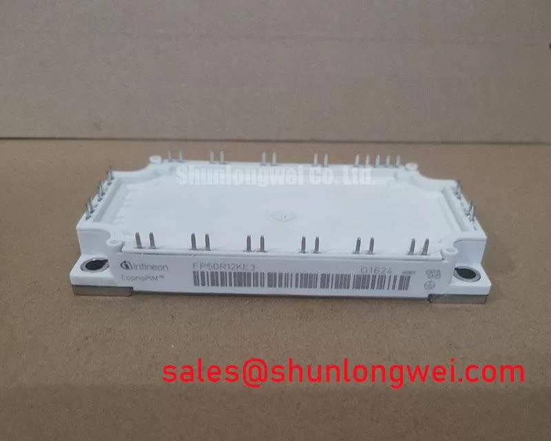
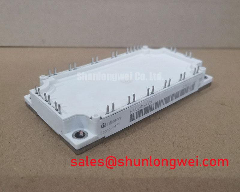
Technical Analysis Based on TRENCHSTOP™ IGBT3
The FP50R12KE3 is built upon Infineon’s TRENCHSTOP™ IGBT3 technology, which represents a significant balance between conduction and switching losses. The module specifies a typical collector-emitter saturation voltage (VCE(sat)) of 1.7V at a nominal current of 50A and a junction temperature of 25°C. This relatively low VCE(sat) directly translates to lower power dissipation during the on-state, which is critical for maintaining high efficiency, especially in applications with long duty cycles.
Effective thermal management is fundamental to the reliability of any power module. The FP50R12KE3 features a junction-to-case thermal resistance (RthJC) of 0.49 K/W for each IGBT. Think of thermal resistance as the width of a pipe for heat; a lower value signifies a wider pipe, allowing heat to escape more easily from the active semiconductor to the heatsink. This efficient heat transfer capability is essential for preventing the device from exceeding its maximum operating junction temperature of 150°C and ensures stable performance under demanding load conditions.
Optimized Application Scenarios
The integrated nature and balanced performance of the FP50R12KE3 make it suitable for several power conversion applications:
- Variable Frequency Drives (VFDs): The six-pack inverter configuration, combined with the integrated rectifier and brake chopper, provides a nearly complete power stage for compact motor drives.
- Industrial Automation & Servo Drives: Its reliability and thermal performance support the precision and high-duty-cycle requirements of modern servo systems.
- Uninterruptible Power Supplies (UPS): The module’s efficiency and 1200V blocking voltage are well-suited for the inverter stage of online UPS systems, ensuring dependable power backup.
- Solar Inverters: In solar applications, the FP50R12KE3 can serve as a durable and efficient DC-AC converter, maximizing energy harvest from photovoltaic arrays.
This module is best matched for systems up to 20 kW requiring a compact, all-in-one power conversion solution.
Key Specification Parameters for FP50R12KE3
| Parameter Category | Value | |
|---|---|---|
| Absolute Maximum Ratings (per switch) | Collector-Emitter Voltage (VCES) | 1200 V |
| Continuous Collector Current (IC @ Tc=80°C) | 50 A | |
| Total Power Dissipation (Ptot @ Tc=25°C) | 280 W | |
| IGBT Electrical Characteristics (Tvj=25°C) | Collector-Emitter Saturation Voltage (VCE(sat), typ. @ IC=50A) | 1.7 V |
| Gate Threshold Voltage (VGE(th)) | 5.0 – 6.5 V | |
| Turn-off Energy (Eoff, typ.) | 5.80 mJ | |
| Thermal & Mechanical | Operating Junction Temperature (Tvj op) | -40 to +150 °C |
| Integrated NTC Thermistor | Yes (R25 = 5 kΩ ±5%) | |
Note: These values are highlights. Engineers must consult the official FP50R12KE3 datasheet for complete specifications and operating curves.
Engineer’s FAQ
- What are the primary thermal design considerations for the FP50R12KE3?
- The primary consideration is ensuring an effective thermal interface between the module’s baseplate and the heatsink. Due to its RthJC of 0.49 K/W per IGBT, proper mounting torque and a uniform layer of thermal interface material are crucial to minimize contact resistance and keep the junction temperature within the safe operating area detailed in the datasheet.
- What is the recommended gate drive voltage?
- The datasheet specifies characteristic values with a gate-emitter voltage (VGE) of +15V for turn-on and recommends a negative voltage for turn-off to improve noise immunity. While the absolute maximum VGE is ±20V, operating at the recommended +15V ensures optimal performance and reliability.
- How does the integrated NTC thermistor function?
- The built-in NTC thermistor provides a means for real-time temperature monitoring. Its resistance changes predictably with temperature (5 kΩ at 25°C). This allows the control system to implement over-temperature protection or dynamic performance adjustments, enhancing overall system robustness. The R/T characteristics are available in the datasheet.
System Integration and Design Enablement
The FP50R12KE3 offers a compelling solution for designers of mid-power drives and inverters. By integrating key power stages into a single, thermally efficient EconoPIM™ 2 package, it allows for a smaller system footprint and simplified assembly. The module’s balanced loss characteristics, a hallmark of its TRENCHSTOP™ IGBT3 technology, enable robust and efficient power conversion across a range of industrial applications. For related technologies, consider exploring Intelligent Power Modules (IPMs) or understanding the fundamentals of IGBT VCE(sat) evolution.