Fuji 7MBR30SA060-50: A Technical Analysis of the 7-in-1 IGBT Power Module
Fuji 7MBR30SA060-50 | 600V 30A 7-in-1 IGBT PIM Module
Introduction and Core Highlights
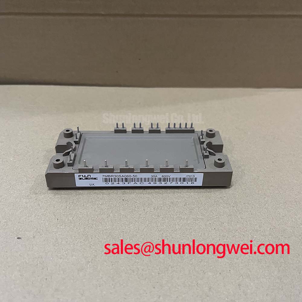
The Fuji Electric 7MBR30SA060-50 is a highly integrated Power Integrated Module (PIM) that combines a three-phase diode bridge converter, a three-phase IGBT inverter, and a brake chopper circuit into a single compact package. This consolidation streamlines the design of low-power motor drives and other power conversion systems by minimizing component count and simplifying PCB layout.
- Core Specifications: 600V | 30A | 7-in-1 Integrated Power Stage
- Key Advantages: Reduces system size and assembly costs; features an integrated NTC thermistor for precise, real-time temperature monitoring.
By providing a complete power core, this module addresses the engineering need for a functionally dense solution in space-constrained applications. It eliminates the complexity of selecting and validating multiple discrete components for the rectifier, inverter, and braking stages.
Download Official Datasheet (PDF)

Technical Analysis of Core Features
The primary engineering value of the 7MBR30SA060-50 lies in its high level of functional integration. A 7-in-1 module contains all the necessary semiconductor switches for a complete AC-DC-AC conversion path with regenerative braking capability. This Power Integrated Module (PIM) approach reduces parasitic inductance between stages compared to a discrete design, which can lead to lower voltage overshoots during switching and improved EMI performance.
Effective thermal management is fundamental to power module reliability. The datasheet specifies a thermal resistance from junction to case (Rth(j-c)) of 0.50°C/W for the inverter IGBT. This value can be thought of as the width of a pipe for heat dissipation; a lower number signifies a wider pipe, allowing heat to be evacuated from the semiconductor junction to the heatsink more efficiently. This is further supported by an integrated NTC thermistor, providing a direct, real-time temperature measurement that enables precise over-temperature protection and system monitoring.
The module’s electrical characteristics are optimized for low to medium frequency applications. The typical collector-emitter saturation voltage (VCE(sat)) is 1.90V at the nominal current and a junction temperature of 125°C. This parameter is a primary contributor to conduction losses, which are often the dominant loss factor in motor control applications. A well-defined VCE(sat) ensures predictable thermal performance and system efficiency.

Optimized Application Scenarios
- Compact Industrial Motor Drives: The all-in-one configuration is ideal for small Variable Frequency Drives (VFDs), reducing the overall drive footprint and simplifying manufacturing.
- HVAC Blowers and Fans: The module’s integration and thermal monitoring capabilities are well-suited for reliable, long-life operation in commercial HVAC systems.
- Pump Controllers: The 7MBR30SA060-50 provides a robust power stage for controlling water pumps and other fluid handling machinery, where compactness can be a key requirement.
- General-Purpose Inverters: Its standard 600V/30A rating makes it a versatile building block for various low-power inverters and power conversion units.
For applications under 10 kW requiring a complete AC-DC-AC power stage with braking, this integrated module is a highly effective solution.
Key Specification Parameters
| Absolute Maximum Ratings (Tc = 25°C unless otherwise specified) | |
|---|---|
| Collector-Emitter Voltage (Vces) | 600V |
| Collector Current (Ic) | 30A (Tc=80°C) |
| Gate-Emitter Voltage (Vges) | ±20V |
| Operating Junction Temperature (Tj) | +150°C |
| Electrical Characteristics (Inverter Part, Tj = 125°C) | |
| Collector-Emitter Saturation Voltage (VCE(sat)) (Typ.) | 1.90V (at Ic=30A, Vge=15V) |
| Turn-on Switching Loss (Eon) (Typ.) | 3.5 mJ/pulse |
| Turn-off Switching Loss (Eoff) (Typ.) | 3.3 mJ/pulse |
| Forward Voltage (FWD) (Vf) (Typ.) | 1.70V (at Ie=30A, Vge=0V) |
Engineer’s FAQ
Q1: What are the main components inside the 7MBR30SA060-50 7-in-1 module?
The module contains three main sections: a three-phase diode bridge rectifier for AC-to-DC conversion, a three-phase IGBT inverter bridge (six IGBTs and six free-wheeling diodes) for DC-to-AC conversion, and a single IGBT with an anti-parallel diode for the brake chopper circuit.
Q2: What is the recommended mounting torque for this module, and why is it critical?
The datasheet specifies a recommended mounting torque of 2.5 to 3.5 Nm for the M5 mounting screws. Applying the correct torque is essential to ensure a low-resistance thermal path to the heatsink. Insufficient torque leads to poor heat transfer, while excessive torque can cause mechanical stress and damage the module’s substrate.
Q3: How is the integrated NTC thermistor used for protection?
The NTC thermistor provides a resistance value that changes predictably with the module’s temperature. A microcontroller or control circuit can monitor this resistance to calculate the module’s operating temperature. If the temperature exceeds a predefined safety limit (e.g., 125°C), the controller can trigger a fault, shut down the gate drive signals, and prevent thermal runaway.
Q4: What is the recommended gate voltage (VGE) for driving the IGBTs?
The datasheet specifies the electrical characteristics using a positive gate voltage of +15V for turning the IGBT on and a negative or zero voltage for turning it off. Operating at the recommended +15V ensures the IGBT reaches its specified low VCE(sat) value, minimizing conduction losses.
Enabling Compact and Reliable Power Design
The 7MBR30SA060-50 module provides a robust, all-in-one power stage that allows engineers to accelerate development and reduce the physical volume of their end systems. Its combination of functional density and integrated thermal feedback makes it a sound foundation for creating efficient and durable low-power motor control and power conversion applications.