MIG75Q7CSB1X 1200V 75A IGBT Module: A Technical Analysis for Inverter Design
MIG75Q7CSB1X | 1200V 75A 6-in-1 IGBT Module
Integrated Power Stage for Three-Phase Inverter Designs
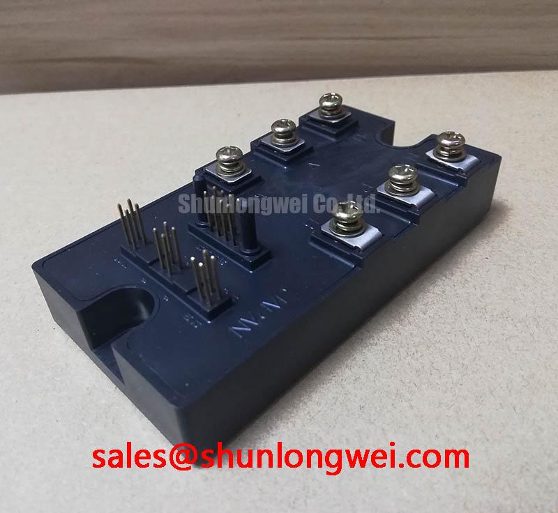
The Toshiba MIG75Q7CSB1X is a high-integration IGBT module that consolidates a complete three-phase inverter bridge into a single, compact package. This module’s primary engineering value lies in its ability to simplify power stage design and assembly by incorporating six 1200V, 75A Insulated Gate Bipolar Transistors (IGBTs) with their corresponding freewheeling diodes. This level of integration reduces component count and minimizes parasitic inductance, which is a key factor in achieving reliable switching performance in motor control systems.
- Core Specifications: 1200V | 75A | 6-in-1 Three-Phase Bridge
- Key Advantages: Streamlines PCB layout and assembly, provides 2500V electrical isolation.
By housing the full power stage in one component, engineers can significantly reduce the complexity of both the electrical layout and the thermal management system.
Download Official Datasheet (PDF)

Technical Analysis of the MIG75Q7CSB1X
A defining feature of the MIG75Q7CSB1X is its integrated six-pack topology. This design inherently minimizes stray inductance between the switching components compared to a solution using six discrete IGBTs. Lower inductance leads to reduced voltage overshoots during high-speed switching events, which enhances system reliability and can simplify the requirements for snubber circuits. The module’s internal layout is engineered to provide a balanced current path for all phases, supporting stable operation in demanding PWM-controlled motor drives.
Effective thermal dissipation is critical for the long-term reliability of any power semiconductor. The MIG75Q7CSB1X specifies a thermal resistance from junction to case (Rth(j-c)) of 0.2 °C/W for each IGBT and 0.33 °C/W for each diode. Thermal resistance can be thought of like the width of a pipe for heat; a lower value signifies a wider pipe, allowing heat to escape the semiconductor die more efficiently. These specified values indicate a high-capacity thermal path to the module’s baseplate, enabling designers to implement an effective cooling strategy and maintain the junction temperature well below the 150°C maximum limit.


Optimized Application Scenarios
The characteristics of this module make it a strong candidate for several medium-power applications.
- AC Motor Drives: Its 1200V breakdown voltage provides a substantial safety margin for 380V and 480V AC line-powered systems, making it ideal for industrial pumps, fans, and conveyors.
- General-Purpose Inverters: The 75A current rating and integrated design offer a robust and space-saving solution for various power conversion tasks.
- Uninterruptible Power Supplies (UPS): The module’s capacity for continuous current and its thermally efficient package are essential for building reliable backup power systems.
This IGBT module provides a well-matched power stage for three-phase inverter systems operating in the 15 to 30 kW range.
Key Specifications of the MIG75Q7CSB1X
| Absolute Maximum Ratings (Ta = 25°C) | |
|---|---|
| Collector-Emitter Voltage (VCES) | 1200 V |
| Gate-Emitter Voltage (VGES) | ±20 V |
| Collector Current (IC) | 75 A |
| Forward Current (Diode) (IF) | 75 A |
| Collector Power Dissipation (PC) | 625 W |
| Operating Junction Temperature (Tj) | 150 °C |
| Isolation Voltage (Visol) | 2500 V (AC, 1 minute) |
| Electrical Characteristics (Ta = 25°C) | |
| Collector-Emitter Saturation Voltage (VCE(sat)) at IC=75A | 2.7 V (Max) |
| Gate-Emitter Leakage Current (IGES) | 0.5 µA (Max) |
| Diode Forward Voltage (VF) at IF=75A | 2.6 V (Max) |
| Turn-On Time (ton) | 1.0 µs (Typ) |
| Turn-Off Time (toff) | 1.5 µs (Typ) |
| Diode Reverse Recovery Time (trr) | 0.35 µs (Typ) |
Engineer’s FAQ
1. What are the typical switching characteristics of the MIG75Q7CSB1X?
Based on the datasheet, under specified test conditions (Vcc=600V, Ic=75A), the typical turn-on time (ton) is 1.0 µs, the turn-off time (toff) is 1.5 µs, and the reverse recovery time (trr) for the internal freewheeling diode is 0.35 µs.
2. What is the maximum case temperature (Tc) this module can handle?
The absolute maximum rating for case temperature is not explicitly stated, but the device parameters are characterized at Tc=125°C. The maximum junction temperature is 150°C. For reliable operation, the thermal design, including the heatsink, must ensure the junction temperature stays below this limit under worst-case operating conditions. A guide on analyzing IGBT failures can provide further context.
3. What is the recommended gate-emitter voltage (VGE) for driving this IGBT?
The datasheet specifies an absolute maximum Gate-Emitter Voltage of ±20V. Standard industry practice for driving an IGBT of this class is to use a positive voltage of +15V for turn-on and a negative voltage between -5V and -10V for a decisive turn-off.
4. Does the MIG75Q7CSB1X include integrated freewheeling diodes?
Yes, each of the six IGBTs within the module is paired with an anti-parallel freewheeling diode. This is essential for applications with inductive loads, such as motor drives, as the diodes provide a path for the inductor current to flow when the IGBT is switched off, protecting the transistor from damaging voltage spikes.
Enabling Robust and Compact Power Designs
The MIG75Q7CSB1X module delivers a practical solution for engineers tasked with developing medium-power three-phase inverters. By integrating the core power switching components into a single, thermally efficient, and electrically isolated package, it provides a solid foundation for building reliable and compact motor controls, UPS systems, and other power conversion equipment.