Mitsubishi CM200DU-12F IGBT Module: A Comprehensive Technical Review
Mitsubishi CM200DU-12F IGBT Module | 600V 200A Dual
Introduction and Core Highlights
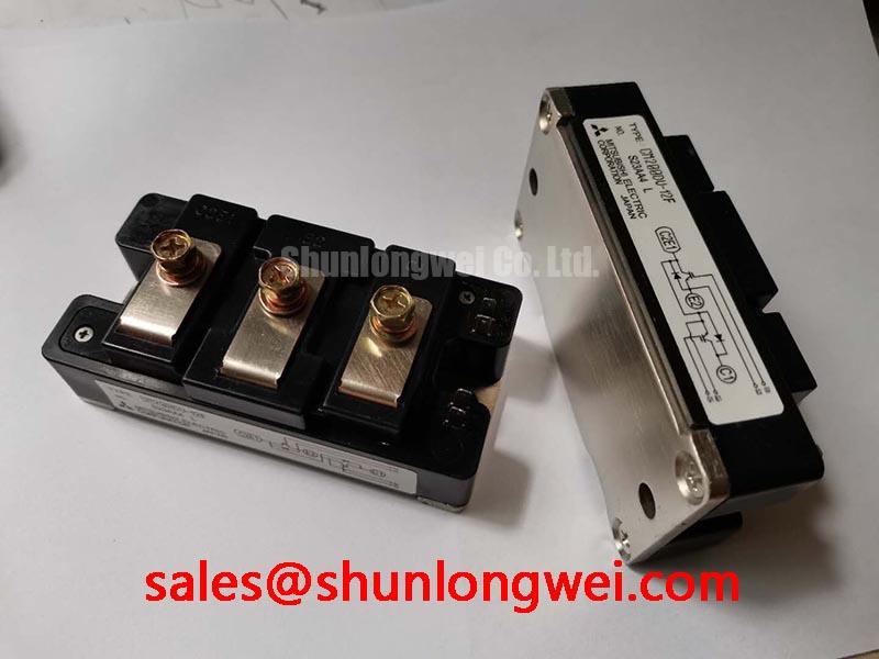
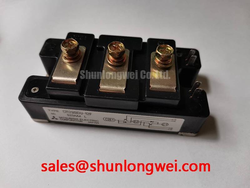
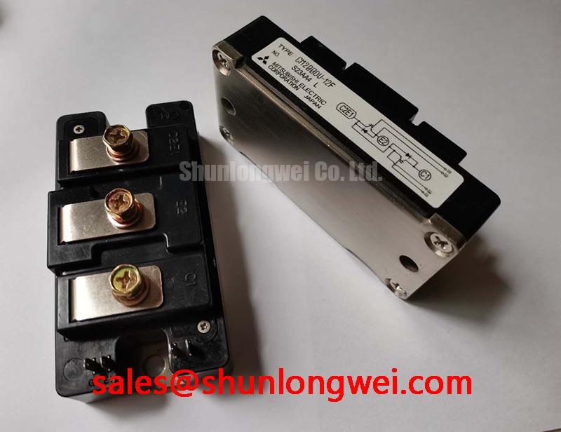
The Mitsubishi CM200DU-12F is a dual IGBT module engineered for robust performance in high-power switching applications. This device integrates two 600V, 200A IGBTs in a half-bridge configuration, delivering a proven, reliable solution for power conversion systems. Its primary value lies in its balanced electrical characteristics and thermal efficiency, providing a durable building block for industrial motor drives and power supplies. It effectively addresses the need for a component that can reliably manage significant power loads in demanding operational cycles.
- Core Specifications: 600V | 200A | VCE(sat) 2.7V (Max)
- Key Advantages: Facilitates simplified three-phase inverter designs, ensures efficient heat dissipation through an isolated baseplate.
Download Official Datasheet (PDF)
Technical Analysis for System Integration
The engineering value of the CM200DU-12F is clearly defined by its electrical and thermal specifications. The maximum collector-emitter saturation voltage (VCE(sat)) is specified at 2.7V with a 200A collector current. This parameter is critical as it directly dictates the conduction losses within the system. A lower VCE(sat) results in less power dissipated as heat during the IGBT’s on-state, which is a key factor for improving the overall energy efficiency of an application like a Variable Frequency Drive (VFD).
Effective thermal management is fundamental to the reliability of any power system. The CM200DU-12F datasheet specifies a thermal resistance from junction to case (Rth(j-c)) of 0.21°C/W for the IGBT part. Think of thermal resistance as the width of a pipe for heat to escape; a lower value signifies a wider pipe, allowing heat to flow more easily from the active semiconductor junction to the heatsink. This defined value is an essential parameter for engineers when calculating the required heatsink performance to maintain the junction temperature below its 150°C maximum rating.
Optimized Application Scenarios
The specifications of the CM200DU-12F make it a suitable component for several demanding industrial applications:
- General Purpose Inverters: The 600V/200A rating is well-suited for 3-phase motor control in manufacturing, HVAC, and pumping systems.
- AC Servo Drives: The module’s switching characteristics support the precise and rapid torque control required in robotics and CNC machinery.
- Uninterruptible Power Supplies (UPS): Its robust current handling capability ensures reliable performance during the critical DC-to-AC conversion stage.
- Welding Power Supplies: The module’s durability is capable of withstanding the high-current, pulsed-load conditions typical in inverter-based welding equipment.
This module is an optimal match for three-phase inverter systems requiring a straightforward, reliable, and thermally manageable power switching solution.
Key Specification Parameters
| Absolute Maximum Ratings (Tj = 25°C) | ||
|---|---|---|
| Parameter | Symbol | Rating |
| Collector-Emitter Voltage | VCES | 600V |
| Gate-Emitter Voltage | VGES | ±20V |
| Collector Current (DC) | IC | 200A |
| Collector Current (Pulse) | ICM | 400A |
| Maximum Power Dissipation | PC | 590W |
| Operating Junction Temperature | Tj | -40 to +150°C |
| Electrical & Thermal Characteristics (Tj = 25°C) | ||
| Collector-Emitter Saturation Voltage (IC=200A) | VCE(sat) | 2.2V (Typ) / 2.7V (Max) |
| Gate-Emitter Threshold Voltage (IC=20mA) | VGE(th) | 5.5V (Typ) |
| Thermal Resistance (Junction to Case, IGBT) | Rth(j-c)Q | 0.21°C/W (Max) |
| Thermal Resistance (Junction to Case, Diode) | Rth(j-c)R | 0.36°C/W (Max) |
Engineer’s FAQ
- What are the optimal gate drive conditions for the CM200DU-12F?
- The datasheet electrical characteristics are specified using a gate-emitter voltage (VGE) of +15V for turn-on and assume a negative voltage for turn-off. For robust operation, particularly in noisy environments, a gate drive supplying a positive voltage of +15V and a negative voltage between -5V and -10V is recommended to ensure full enhancement and prevent unintended turn-on.
- How should the CM200DU-12F be mounted to a heatsink for proper thermal performance?
- To achieve the specified thermal resistance, the module’s baseplate must be mounted to a flat, clean heatsink surface using a thin, uniform layer of thermal grease (e.g., Shin-Etsu G-746 or equivalent). The datasheet indicates M6 mounting holes; these should be tightened to the recommended torque of 3.0-4.0 N·m to ensure proper contact without inducing mechanical stress on the module.
- What is the function of the integrated free-wheeling diode?
- The internal free-wheeling diode (FWD) provides a path for inductive load current when the IGBT is turned off. The FWD in the CM200DU-12F is a super-fast recovery type, which minimizes reverse recovery losses and voltage spikes during switching. This is critical for improving the efficiency and reliability of motor drive applications.
- Is this module suitable for high-frequency switching?
- The CM200DU-12F is part of Mitsubishi’s standard F-series, optimized for general-purpose applications typically operating in the low to mid-kHz range (e.g., 2-15 kHz). While its switching times are defined, it is not intended for very high-frequency designs where devices like SiC modules would be more appropriate. A review of the switching loss curves in the datasheet is necessary to confirm performance at a specific target frequency.
Concluding Statement
The CM200DU-12F IGBT module offers a solid, industry-standard solution for power electronics engineers. Its dual configuration in a single package and well-defined thermal characteristics provide a reliable foundation for developing efficient and durable power conversion systems for a wide range of industrial machinery.