A Technical Review of the Infineon DDB6U215N16L Rectifier Module
DDB6U215N16L: Infineon 1600V, 215A Diode Module
Introduction and Core Highlights
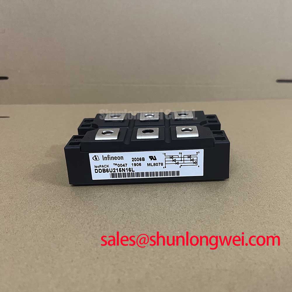
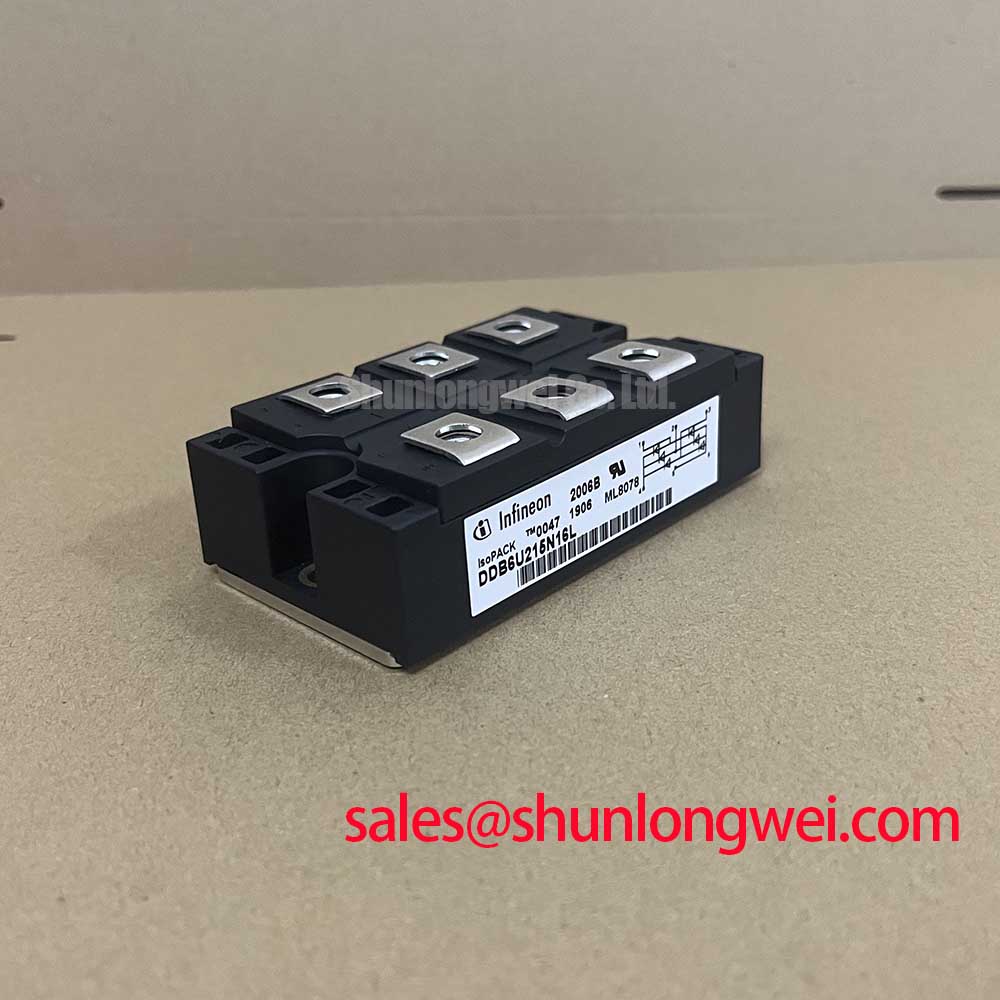
The Infineon DDB6U215N16L is a three-phase uncontrolled rectifier bridge module engineered for high-reliability AC-to-DC power conversion. Its primary value lies in delivering exceptional surge current survivability and high thermal efficiency within a standard industrial housing. This focus on robustness ensures stable DC bus voltage for the front-end of high-power systems.
- Core Specifications: 1600 V | 215 A | IFSM 2300 A
- Key Advantages: High resilience against line transients, efficient heat dissipation via an isolated baseplate.
By integrating six diodes into a single package, the DDB6U215N16L simplifies assembly and improves thermal performance compared to discrete solutions, directly addressing the challenge of creating compact, reliable power stages. For access to detailed electrical and thermal characteristics, you can Download the Official Datasheet (PDF).

Technical Analysis: Built for Industrial Demands
A critical parameter for rectifiers in industrial environments is the non-repetitive surge current (IFSM). The DDB6U215N16L boasts an IFSM rating of 2300 A (at 10ms, Tvj=25°C), providing a substantial safety margin. This capability is vital for handling the large inrush currents that occur when charging DC-link capacitors in motor drives or UPS systems, preventing module failure during startup or under fault conditions.
Effective thermal management is equally important for reliability. The module’s thermal resistance from junction to case (Rth(j-c)) is specified per diode. You can think of thermal resistance as the width of a pipe for heat; a lower value means heat escapes more easily. The module’s design facilitates efficient heat transfer to an external heatsink, a key factor in maintaining performance during continuous high-current operation and achieving a longer operational lifespan as discussed in IGBT thermal design guides.
Optimized Application Scenarios
The specific characteristics of the DDB6U215N16L make it a strong candidate for several demanding applications:
- Variable Frequency Drives (VFDs): Its high VRRM of 1600V provides excellent protection against voltage transients on the AC line, ensuring a stable DC bus for the inverter stage.
- Uninterruptible Power Supplies (UPS): The high surge current rating is crucial for managing the transition to battery power and handling the initial load demand without component stress.
- Welding Power Supplies: The module’s robust thermal performance allows it to handle the high, often pulsed, current loads typical in welding applications, delivering a consistent DC output for a stable arc.
- Industrial Power Supplies: For general high-power AC-DC conversion, the integrated design simplifies manufacturing and improves the overall reliability and power density of the final system.
Its combination of high voltage overhead and superior surge handling makes this module best suited for front-end rectifiers in systems operating on 400V to 690V AC lines.
Key Specifications of the DDB6U215N16L
| Electrical and Thermal Characteristics (TC = 80°C unless otherwise specified) | |
|---|---|
| Repetitive Peak Reverse Voltage (VRRM) | 1600 V |
| Average Forward Current (IdAV) | 215 A |
| Surge Forward Current (IFSM, 10ms, Tvj=25°C) | 2300 A |
| Maximum Junction Temperature (Tvj max) | 150 °C |
| Isolation Test Voltage (VISOL, RMS, 50Hz, 1 min) | 3600 V |
Engineer’s FAQ
1. How is the total power dissipation calculated for this three-phase rectifier module?
To a first approximation for each diode, you can calculate conduction loss using the forward voltage parameters from the datasheet: Ploss = VF0 * IF(AV) + rf * IF(RMS)2. The datasheet provides these threshold voltage and slope resistance values. Total module loss is the sum of losses for all six diodes under the specific load conditions.
2. What are the mounting considerations for the DDB6U215N16L?
Proper mounting is crucial for effective cooling. The datasheet specifies a mounting torque for the power terminals and the module’s baseplate screws. Applying the correct torque with a thermal interface material (TIM) ensures minimal thermal resistance between the module’s baseplate and the heatsink. This is a foundational aspect of high-voltage IGBT reliability and applies equally here.
3. What does the “uncontrolled rectifier” designation mean?
It means the module uses diodes, which are passive components. They conduct whenever the forward voltage is positive. This is distinct from a “controlled rectifier,” which uses thyristors (SCRs) that require a gate signal to turn on, allowing for control over the output DC voltage.
4. Is this module suitable for applications requiring paralleling?
While the datasheet does not explicitly detail paralleling procedures, modules can often be paralleled if proper thermal and electrical balancing is implemented. Engineers considering this should analyze the V-I characteristics and consult further application notes on balancing currents between parallel modules. Understanding topics like parasitic inductance is also important in such designs.
Design Enablement
The DDB6U215N16L offers a direct path to developing resilient and thermally stable AC-DC front-ends. Its high voltage margin and surge current capacity provide the necessary robustness for industrial power systems, while the integrated module design simplifies the mechanical and thermal engineering effort.