Mitsubishi CM75E3Y-24E 1200V 75A IGBT Module: Technical Analysis and Application Guide
Mitsubishi CM75E3Y-24E 1200V 75A IGBT Power Module
The Mitsubishi CM75E3Y-24E is a high-performance Insulated Gate Bipolar Transistor (IGBT) module belonging to the sixth-generation E-Series, engineered for high-power switching and industrial motor control. This module integrates a 1200V / 75A rating into a compact, thermally optimized package, providing a balance between high-frequency capability and low conduction losses.
- Core Specifications: 1200V | 75A | VCE(sat) 2.1V (Typical)
- Key Advantages: Significant reduction in power dissipation and optimized thermal cycling for extended operational life.
One common concern for engineers is how the 1200V rating impacts the thermal management strategy in high-density inverter designs. The CM75E3Y-24E addresses this through its integrated trench-gate architecture, which minimizes conduction losses and simplifies the cooling requirements for the overall system.
Download Official Datasheet (PDF)
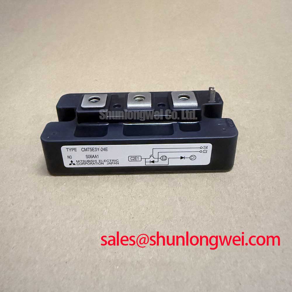
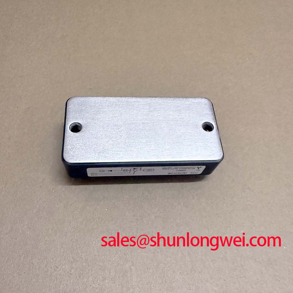
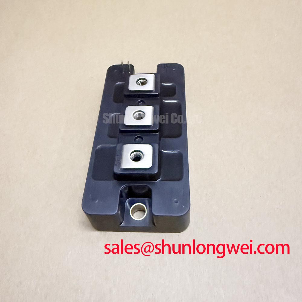
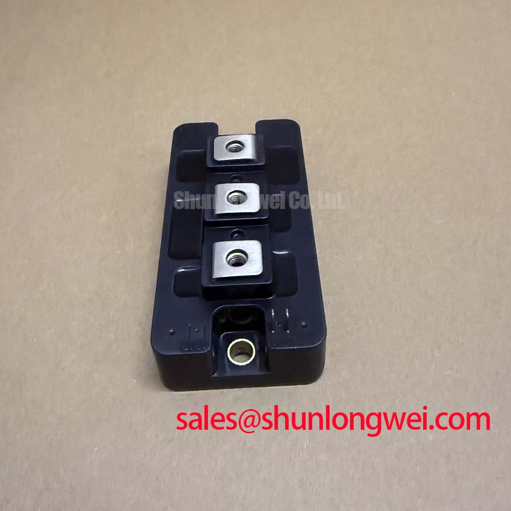
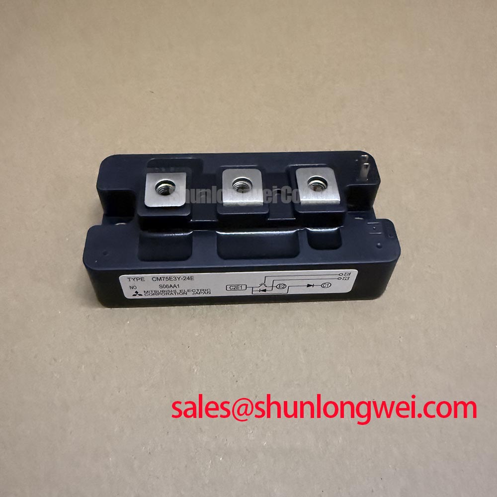
Technical Analysis of the E-Series UVP
The Unique Value Proposition (UVP) of the CM75E3Y-24E lies in its 6th Generation Trench Gate CSTBT™ technology. Unlike standard planar structures, the trench gate design allows for a higher cell density. This directly influences the VCE(sat), allowing the device to carry 75A of current with minimal voltage drop. In engineering terms, this translates to lower conduction energy waste.
To better understand this, one can use a “traffic flow” analogy: imagine a multi-lane highway. Planar technology is like a two-lane road where cars (electrons) often get congested, creating friction and heat. The trench technology in the CM75E3Y-24E is like adding multiple elevated lanes; the same number of cars can move much faster and with significantly less friction, allowing the heat to stay within manageable limits even at peak loads. This architecture is vital for preventing premature IGBT failure due to localized overheating.
Furthermore, the module is designed with a low-inductance package. High parasitic inductance can lead to destructive voltage spikes during high-speed switching. By optimizing the internal lead frames and terminal spacing, the CM75E3Y-24E ensures that the Reverse Bias Safe Operating Area (RBSOA) is maximized, allowing for safer turn-off transitions even under heavy inductive loads.
Optimized Application Scenarios
Given its 1200V / 75A rating, the CM75E3Y-24E is best suited for medium-power industrial environments where efficiency and long-term reliability are paramount.
- Variable Frequency Drives (VFDs): Ideal for 400V/480V AC motor control where the 1200V rating provides a sufficient safety margin against line surges.
- Solar Inverters: The low switching losses of the E-Series help maximize the energy harvest efficiency in string inverters.
- Uninterruptible Power Supplies (UPS): Specifically used in the output inverter stage where the high-speed switching capability ensures a clean sine wave output.
- Welding Power Supplies: Suitable for industrial welders that require robust thermal cycling capability under pulsed-load conditions.
Best Match Conclusion: For 480V industrial motor drives, the CM75E3Y-24E provides an optimal balance of 1200V headroom and 75A current density for high-efficiency inverter stages.
Key Specifications Table
| Category | Parameter | Typical Value |
|---|---|---|
| Absolute Maximum Ratings | Collector-Emitter Voltage (VCES) | 1200V |
| Collector Current (IC) | 75A | |
| Electrical Characteristics | VCE(sat) @ IC=75A, Tj=25°C | 2.1V |
| Gate-Emitter Threshold Voltage (VGE(th)) | 6.0V – 7.5V | |
| Thermal Characteristics | Thermal Resistance (Rth(j-c)) – IGBT | 0.17 K/W |
| Junction Temperature (Tj) Range | -40 to +150°C |
Engineer FAQ
Q1: What is the recommended mounting torque for the CM75E3Y-24E terminals and baseplate?
According to the Mitsubishi installation guidelines, the recommended mounting torque for M5 screws (both terminals and baseplate) is typically 2.5 to 3.5 N·m. Over-tightening can cause internal package stress, while under-tightening increases electrical and thermal resistance.
Q2: How does the CM75E3Y-24E handle short-circuit conditions?
The module is designed to withstand a short circuit for a duration (tsc) of up to 10μs, provided the collector-emitter voltage remains below 800V and the junction temperature starts at or below 125°C. This provides a critical time window for the gate driver’s protection circuits to activate.
Q3: Is it necessary to use a negative gate bias for this module?
While the CM75E3Y-24E can operate with a 0V turn-off voltage, using a negative gate voltage (e.g., -5V to -15V) is highly recommended. This improves noise immunity and prevents parasitic turn-on caused by Miller capacitance during high dV/dt switching events.
The Mitsubishi CM75E3Y-24E stands as a cornerstone component for power engineers requiring reliable 1200V switching. By leveraging its low thermal resistance and advanced trench-gate architecture, designers can achieve higher power densities and improved system efficiency across a wide range of industrial applications. Its robust design ensures performance stability even in the most demanding electromagnetic environments.