Mitsubishi QM30DY-H: A Technical Guide to the 600V/30A Dual Transistor Module
Mitsubishi QM30DY-H: 600V 30A Dual Transistor Module
Engineered for Efficient Medium-Power Switching
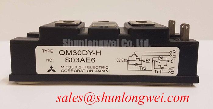
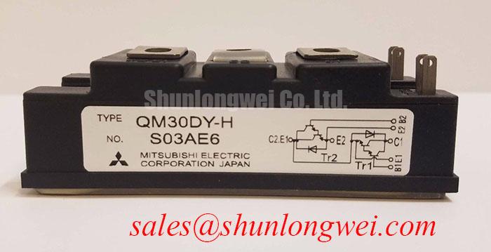
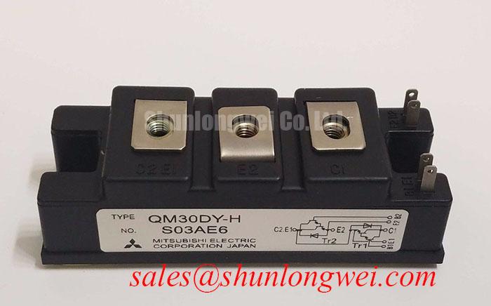
The Mitsubishi QM30DY-H is a dual Darlington transistor module from the H-Series, providing a robust and efficient solution for medium-power switching applications. It integrates two transistors in a half-bridge configuration within a single insulated package, streamlining the design of compact inverters and motor controllers. This module is specified for its balance of current handling and voltage blocking capability, making it a reliable component for demanding industrial systems.
- Core Specifications: 600V | 30A | hFE of 75 (min)
- Key Advantages: Integrated dual-transistor design simplifies assembly. Isolated baseplate enhances safety and thermal performance.
- Design Application: This analysis provides key electrical and thermal parameters to support accurate heatsink selection and reliable gate drive implementation.
Download Official Datasheet (PDF)
Technical Analysis for System Integration
A critical parameter for power module performance is the collector-emitter saturation voltage, VCE(sat). For the QM30DY-H, the maximum VCE(sat) is specified at 2.7V with a collector current of 30A. This value is a direct indicator of conduction losses; a lower VCE(sat) results in less power dissipated as heat when the transistor is fully on. This efficiency is crucial for minimizing the thermal load on the heatsink and improving the overall energy efficiency of the end application, such as a variable frequency drive (VFD).
Effective thermal management is essential for long-term reliability. The module’s thermal resistance from junction to case, Rth(j-c), is documented as 0.5°C/W per transistor. This value can be thought of as the width of a pipe for heat flow; a lower thermal resistance allows heat to escape the semiconductor junction more easily. This efficient heat transfer capability, combined with the module’s isolated mounting base, allows for robust operation by preventing the junction temperature from exceeding its maximum rating of 150°C.
Optimized Application Scenarios
The QM30DY-H is well-suited for a range of power conversion and motion control systems. Its characteristics make it particularly effective in the following roles:
- AC Motor Controllers: The dual-device configuration is ideal for building one leg of a three-phase inverter, reducing component count and simplifying the PCB layout.
- Uninterruptible Power Supplies (UPS): Its 600V blocking voltage and 30A current rating provide sufficient headroom and power handling for medium-sized UPS inverter stages.
- DC Motor Controllers: The module’s robust DC current gain (hFE) and power dissipation capacity are beneficial for chopper and H-bridge circuits used in DC motor control.
- Welding Power Supplies: The surge current capability (ICSM of 300A) allows the module to handle the pulsed power demands characteristic of welding applications.
Its specifications make the QM30DY-H an excellent match for power systems requiring robust switching of up to 30A with straightforward thermal design.
Key Specifications of the QM30DY-H
| Absolute Maximum Ratings (Tj=25°C) | ||
|---|---|---|
| Parameter | Symbol | Value |
| Collector-Emitter Voltage | VCEX | 600V |
| Collector Current (DC) | IC | 30A |
| Collector Power Dissipation | PC | 250W |
| Junction Temperature | Tj | -40 to +150°C |
| Isolation Voltage | Viso | 2500V (AC, 1 minute) |
| Electrical Characteristics (Tj=25°C) | ||
| Collector-Emitter Saturation Voltage (IC=30A, IB=0.4A) | VCE(sat) | 2.7V (Max) |
| DC Current Gain (IC=30A, VCE=2V) | hFE | 75 (Min) |
| Turn-On Time (ton) | ton | 4.0µs (Typ) |
| Turn-Off Time (tf) | tf | 2.0µs (Typ) |
| Thermal Resistance (Junction to Case, Transistor) | Rth(j-c)Q | 0.5°C/W (Max) |
Engineer’s FAQ
1. How does the Rth(j-c) value influence heatsink selection?
The thermal resistance from junction to case, Rth(j-c), is a critical value for thermal calculations. To choose an appropriate heatsink, you must calculate the total power dissipation based on conduction and switching losses. This power value, multiplied by the sum of Rth(j-c) and the heatsink’s thermal resistance (Rth(c-s) + Rth(s-a)), must keep the junction temperature below its 150°C maximum. A lower Rth(j-c) like the 0.5°C/W of the QM30DY-H allows for a smaller or more cost-effective heatsink for a given power dissipation.
2. What are the mounting considerations for this module?
The QM30DY-H features an electrically isolated baseplate with a rated isolation voltage of 2500V. When mounting to a heatsink, it is essential to apply a thin, even layer of thermal grease to ensure optimal heat transfer (contact thermal resistance Rth(c-f) is specified as 0.05°C/W with grease). The recommended mounting torque for the M5 main terminal screws is between 1.47 and 1.96 N·m. Over-torquing can damage the module, while under-torquing can lead to poor electrical and thermal contact.
3. What is the typical application frequency for this Darlington module?
Based on the typical switching times (ton ≈ 4.0µs, tf ≈ 2.0µs), the QM30DY-H is best suited for low to medium frequency applications. While the maximum frequency depends on many factors, including gate drive and thermal design, it generally performs optimally in systems operating up to a few kilohertz, such as standard AC motor drives and UPS systems. For higher frequencies, a device with faster switching times, such as an IGBT module, might be more appropriate.
4. Can the internal free-wheeling diodes be used for inductive loads?
Yes, each transistor within the QM30DY-H module includes an integrated free-wheeling diode connected in anti-parallel. These diodes are essential for providing a path for inductive load currents when the transistor is switched off, protecting the device from damaging voltage spikes. The diode’s forward voltage is specified alongside the VCE(sat) in the datasheet’s characteristic curves.
Enabling Reliable Power Conversion
The Mitsubishi QM30DY-H transistor module offers a proven, integrated solution for controlling medium-power loads. Its balanced electrical characteristics and robust thermal design empower engineers to build efficient and reliable power conversion systems while simplifying mechanical assembly and thermal management.