SKM300GB12T4 IGBT Module: A Technical Analysis for High-Power Applications
## SKM300GB12T4: Semikron 1200V 300A IGBT Module Analysis
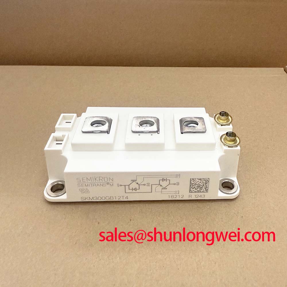
The Semikron SKM300GB12T4 is a half-bridge IGBT module that integrates 4th generation trench gate (IGBT4) technology with a complementary CAL4 freewheeling diode. This combination delivers a balanced performance profile, marked by low conduction losses and robust, soft-switching behavior. It is engineered for power conversion systems where efficiency and reliability are primary objectives. The module’s architecture provides a solid foundation for developing high-power inverters and drives that operate under demanding conditions.
* **Core Specifications**: 1200V | 300A (Nominal) | VCE(sat) 1.7V (typ.)
* **Key Engineering Advantages**:
* Reduced thermal load due to low VCE(sat) and optimized switching energy.
* Enhanced system reliability from the soft-recovery characteristics of the CAL4 diode.
Download Official SKM300GB12T4 Datasheet (PDF)
Technical Analysis: Efficiency and Reliability by Design
The performance of the SKM300GB12T4 is rooted in its core semiconductor technologies and packaging. The use of IGBT4 trench gate silicon results in a low typical collector-emitter saturation voltage (VCE(sat)) of 1.7V at its nominal current of 300A (Tj=25°C). This parameter is crucial for system efficiency. Think of VCE(sat) as a tollbooth for electrical current; a lower value represents a wider, more efficient lane. It allows more current to pass through with less energy wasted as heat, which directly reduces cooling system requirements and operating costs.
Paired with the IGBT is a 4th generation CAL (Controlled Axial Lifetime) freewheeling diode. This diode is engineered for soft and fast recovery characteristics. When the IGBT turns off, the diode takes over the current flow, and a “soft” recovery prevents sharp voltage spikes and reduces electromagnetic interference (EMI). This inherent softness can simplify or even eliminate the need for external snubber circuits, contributing to a more compact and reliable system design. This synergy between the IGBT and diode is critical for hard-switching applications. For a deeper dive into this topic, consider reading about the role of the freewheeling diode.
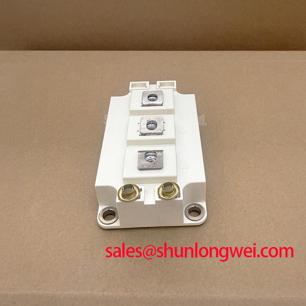
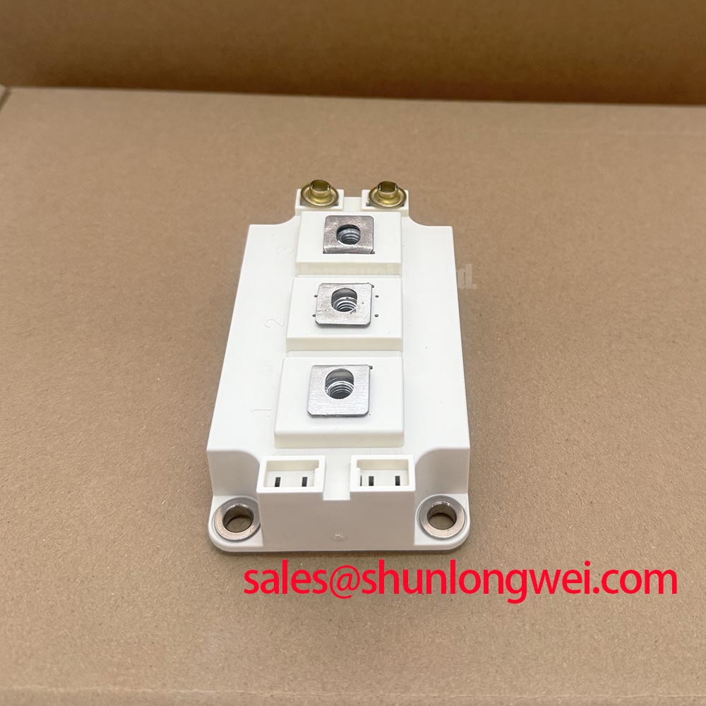
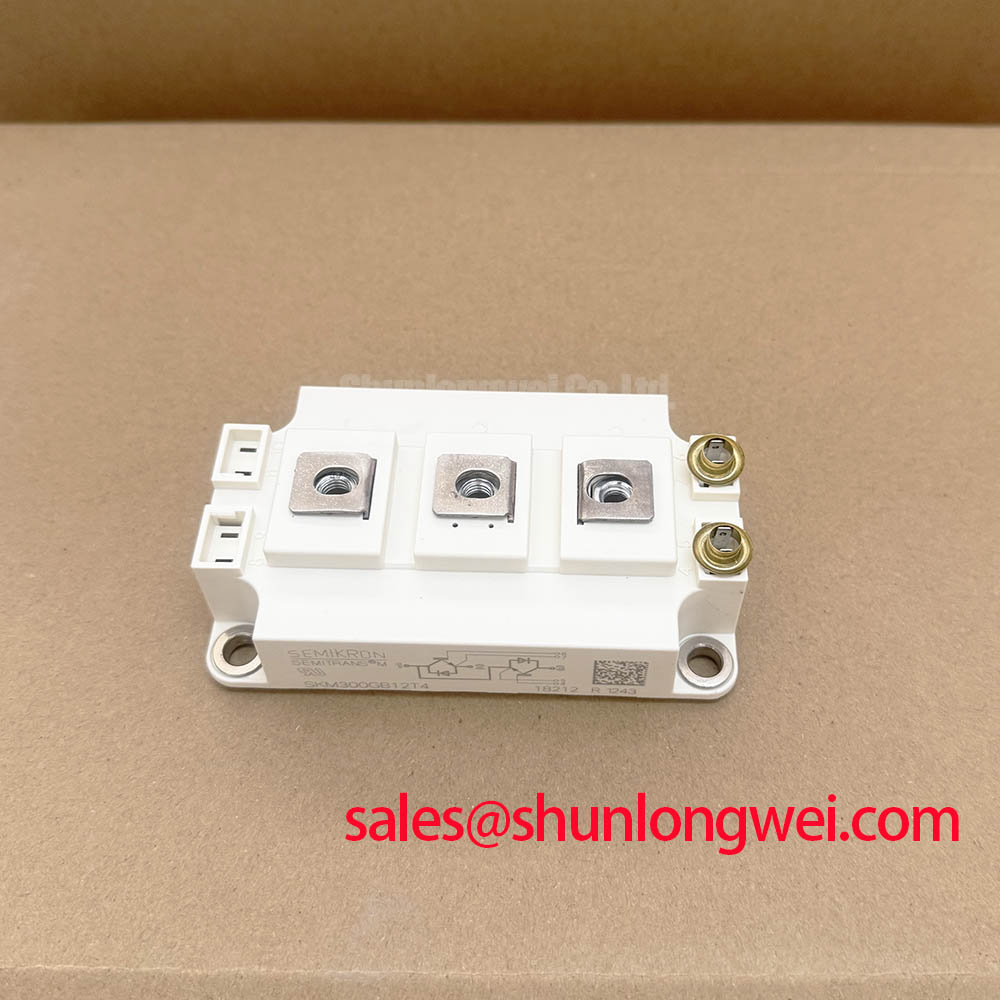
The module is housed in the SEMITRANS 2 package, which features a DBC (Direct Bonded Copper) substrate and an electrically isolated baseplate. This construction provides an isolation voltage (Visol) of 2500V (AC, 1 minute), ensuring safety in high-voltage systems. The thermal resistance from junction to case (Rth(j-c)) per IGBT is specified at a maximum of 0.11 K/W, a key figure for effective thermal management and heatsink design.
### Optimized Application Scenarios
The SKM300GB12T4’s specifications make it a strong candidate for several high-power applications:
* **Variable Frequency Drives (VFDs):** Its low conduction losses are beneficial for motor control, where high torque at low speeds is required. The robust short-circuit withstand time of 10 µs provides critical protection.
* **Uninterruptible Power Supplies (UPS):** The module’s ability to handle a repetitive peak current (ICRM) of 600A ensures it can manage high inrush currents and transient loads reliably.
* **Solar Inverters:** In large-scale solar applications, the 1200V blocking voltage offers sufficient design margin, while the high efficiency (low VCE(sat) and Ets) maximizes energy conversion.
* **Electronic Welding:** The module’s capability to operate at switching frequencies up to 20 kHz and its thermal stability are well-suited for high-frequency welding power supplies.
This module is best matched for three-phase inverter systems up to 150 kVA requiring a balance of efficiency, robustness, and thermal performance.
### Key Specifications of the SKM300GB12T4
| Parameter | Symbol | Value | Unit |
|—|—|—|—|
| **Absolute Maximum Ratings** | | | |
| Collector-Emitter Voltage | VCES | 1200 | V |
| DC Collector Current (TC = 25°C) | IC | 412 | A |
| Repetitive Peak Collector Current | ICRM | 600 | A |
| Gate-Emitter Voltage | VGES | ±20 | V |
| Short Circuit Withstand Time | tpsc | 10 | µs |
| Isolation Test Voltage | Visol | 2500 | V |
| **IGBT Characteristics (Tj = 25°C)** | | | |
| Collector-Emitter Saturation Voltage (IC,nom = 300A) | VCE(sat) | 1.7 (typ.), 2.15 (max.) | V |
| Gate Threshold Voltage | VGE(th) | 5.8 (typ.) | V |
| **Diode Characteristics (Tj = 25°C)** | | | |
| Forward Voltage (IF,nom = 300A) | VF | 1.75 (typ.), 2.1 (max.) | V |
| **Thermal and Mechanical** | | | |
| Max. Junction Temperature | Tj,max | 175 | °C |
| Thermal Resistance, Junction to Case (per IGBT) | Rth(j-c) | 0.088 (typ.), 0.11 (max.) | K/W |
| Mounting Torque (Terminals) | – | M6: 3-5 | Nm |
| Mounting Torque (Case) | – | M6: 3-5 | Nm |
Note: All specifications are cited from the official manufacturer datasheet at typical or specified conditions. Designers must consult the full datasheet for complete characteristic curves and application notes.
Engineer’s FAQ
1. How does the Rth(j-c) of the SKM300GB12T4 impact heatsink selection?
The thermal resistance from junction to case, Rth(j-c), is a critical parameter for thermal design. The SKM300GB12T4 specifies a maximum Rth(j-c) of 0.11 K/W for the IGBT. This low value signifies efficient heat transfer from the semiconductor die to the module’s baseplate. A lower Rth(j-c) allows for a smaller, more cost-effective heatsink for a given power dissipation, or enables the module to operate at higher power levels while keeping the junction temperature within safe limits.
2. What are the recommended mounting practices for this SEMITRANS 2 module?
The datasheet specifies a mounting torque of 3 to 5 Nm for the M6 case mounting screws and the M6 power terminals. It is crucial to apply even pressure and use a calibrated torque wrench to ensure optimal thermal contact between the module baseplate and the heatsink. For gate drive connections, using the dedicated Kelvin emitter (auxiliary emitter) terminal is highly recommended to minimize the impact of stray inductance in the main current path, leading to cleaner and more reliable switching. For more insights on this, review our guide on robust gate drive design.
3. What is the main benefit of the Trench IGBT4 technology in this module?
The primary benefit of Trench IGBT4 technology is its ability to provide a low on-state voltage (VCE(sat)) while maintaining controlled switching losses. This breaks the traditional trade-off where reducing conduction losses often led to higher switching losses. For a power system, this translates directly to higher overall efficiency, as less energy is wasted during both the ‘on’ state and during the switching transitions.
4. Can this module be used in a parallel configuration for higher current?
Yes, but with careful design considerations. The positive temperature coefficient of VCE(sat) at higher currents, a characteristic of IGBT4 technology, helps promote balanced current sharing between paralleled modules. However, to ensure reliability, it is essential to implement a symmetrical busbar layout to equalize stray inductances and ensure simultaneous switching. Asymmetrical layouts can lead to current imbalance and potential module failure.
Design Enablement
By combining the low-loss characteristics of IGBT4 silicon with the soft-switching performance of a CAL4 diode, the SKM300GB12T4 provides a robust and efficient building block for modern power electronics. Its thermally efficient and electrically isolated package simplifies system integration, empowering engineers to develop compact and reliable high-power conversion systems.