T640N14TOF Thyristor: A Technical Guide for High-Power Applications
T640N14TOF: Phase Control Thyristor for High-Power Systems
Introduction to the T640N14TOF Thyristor Module
The Infineon T640N14TOF is a high-reliability phase control thyristor engineered for demanding power conversion and control applications. This device’s primary value proposition is its combination of high surge current capability and robust electrical blocking characteristics, delivered in a hermetically sealed ceramic disc housing. This design ensures stable operation under demanding industrial conditions.
- Core Specifications: 1400V | 644A (Avg) | 9400A (Surge)
- Key Advantages: High overload survivability, suitability for series/parallel connection for power scaling.
- Engineering Insight: The device’s high di/dt and dv/dt capabilities allow it to function reliably in circuits with rapid changes in current and voltage, preventing unintended activation.
Download Official Datasheet (PDF)
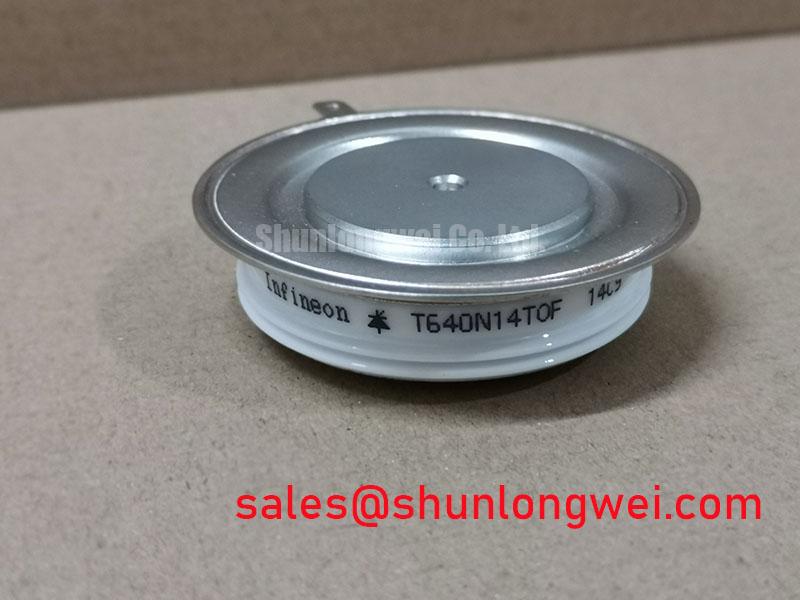
Visual and Mechanical Overview

Technical Analysis for System Integration
The T640N14TOF is defined by its robustness. A critical parameter is its non-repetitive surge current (ITSM) rating of 9400A. This high value indicates a strong tolerance for fault conditions, such as initial inrush currents in large motor drives or short circuits in power supplies. This capability can allow for a “fuseless” design approach in certain systems, reducing component count and potential points of failure.
Another key aspect is the module’s thermal impedance. The low thermal resistance from junction to case (RthJC) is crucial for effective heat dissipation. Think of thermal resistance as the width of a pipe for heat flow; a lower value means a wider pipe, allowing heat to escape the semiconductor junction more easily. This efficiency in heat transfer is fundamental to maintaining the device’s junction temperature (Tvj max of 125°C) within its safe operating area, especially under high continuous current loads.
The device’s disc package, often called a “puk” or “press-pack” housing, is designed for double-sided cooling. This requires a specific mounting procedure with a defined clamping force (6 to 12 kN) to ensure minimal thermal and electrical resistance between the module and the heatsinks. Proper mounting is essential to leverage the full thermal performance of this power semiconductor device.
Optimized Application Scenarios
The specific characteristics of the T640N14TOF make it a strong candidate for several high-power industrial applications:
- Controlled Rectifiers: Its high blocking voltage of 1400V and average current of 644A are ideal for the input stages of high-power AC-DC converters.
- Soft Starters for AC Motors: The thyristor’s ability to precisely control the voltage ramp-up is perfect for reducing mechanical stress and electrical inrush current when starting large induction motors.
- DC Choppers & Static VAR Compensators: The fast turn-on characteristics and high di/dt rating ensure efficient switching in DC power control and grid stability applications.
- Welding Power Supplies: The exceptional surge current capability allows the device to withstand the demanding, pulsed-load conditions found in industrial welding equipment.
This thyristor is best matched for applications requiring robust, reliable AC power control at current levels above 500A where overload survivability is critical.
Key Specifications of the T640N14TOF
| Parameter | Value |
|---|---|
| Repetitive Peak Off-State and Reverse Voltage (VDRM, VRRM) | 1400 V |
| Average On-State Current (ITAV) @ TC=85°C | 644 A |
| RMS On-State Current (ITRMS) | 1450 A |
| Surge Current (ITSM) @ 10 ms, 50 Hz | 9400 A |
| Critical Rate of Rise of Off-State Voltage (dv/dt) | 1000 V/µs |
| Max. On-State Voltage (VTM) @ IT=2000A, Tvj=125°C | 2.15 V |
| Gate Trigger Current (IGT) | 250 mA |
| Operating Junction Temperature (Tvj op) | -40 to +125 °C |
| Clamping Force (FM) | 6 – 12 kN |
Engineer’s Frequently Asked Questions
1. What is the correct mounting procedure for the T640N14TOF to ensure proper thermal contact?
The T640N14TOF requires a clamping force between 6 kN and 12 kN applied evenly across its contact surfaces. It is critical to use a calibrated mounting clamp and ensure that the heatsink surfaces are clean, flat, and coated with a thin, uniform layer of thermal compound to achieve the specified thermal resistance.
2. Can multiple T640N14TOF modules be used in parallel for higher current?
Yes, the datasheet indicates the device is designed for series and parallel connections. For parallel operation, it’s recommended to match devices based on their on-state voltage (VTM) to ensure balanced current sharing. Using reactors or ensuring symmetrical busbar layout can also aid in effective sharing.
3. What does the high dv/dt rating signify for my application?
The high dv/dt capability (1000 V/µs) indicates excellent immunity to false triggering caused by rapid voltage changes across the thyristor, which is common in noisy industrial environments or in circuits with high switching frequencies. This robustness simplifies the design of snubber circuits.
4. Is this thyristor suitable for high-frequency applications?
This is a phase-control thyristor, not a fast-switching GTO or IGCT. Its turn-off time (tq) is 250 µs, making it suitable for line-frequency applications (50/60 Hz) and low-frequency DC choppers, but not for high-frequency inverters where faster switching devices like IGBTs or SiC modules are required.
Enabling Robust Power Control Designs
This device delivers a well-defined set of electrical and thermal characteristics for engineers developing high-power control systems. The T640N14TOF provides the high current capacity and overload resilience necessary for reliable operation in industrial rectifiers and motor control systems. Its design facilitates effective thermal management, a cornerstone of long-term system reliability.