Technical Overview of the CP30TD1-12Y: Mitsubishi’s Integrated 600V 30A CIB IGBT Module
CP30TD1-12Y Mitsubishi IGBT Module: Integrated 600V 30A CIB Technical Overview
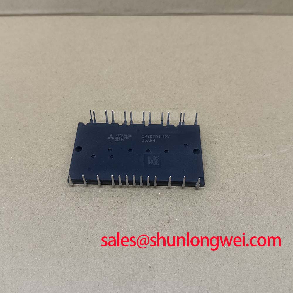
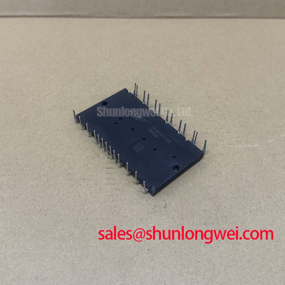
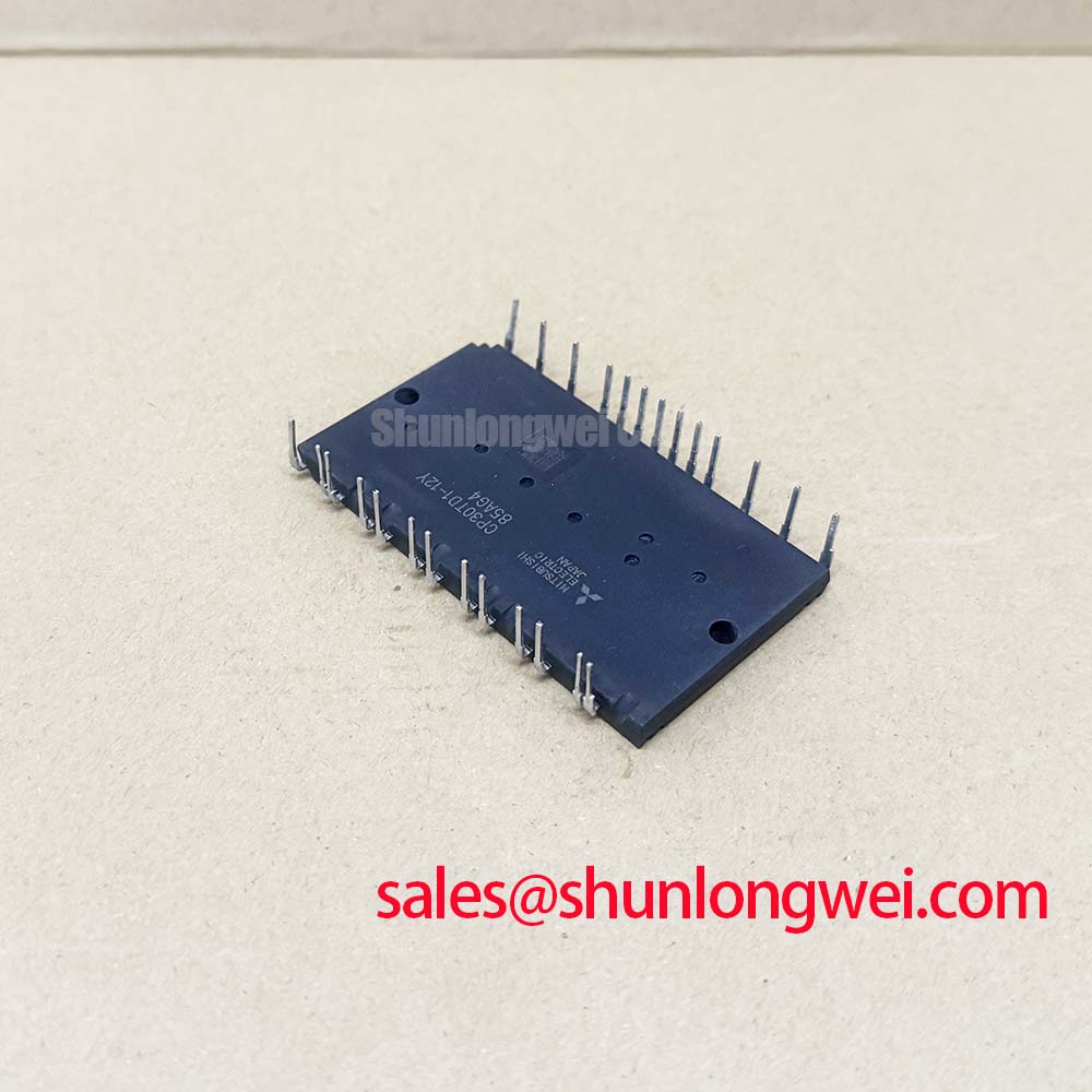
The CP30TD1-12Y is a highly integrated power semiconductor module developed by Mitsubishi Electric, specifically engineered for space-constrained industrial motor control applications. This module utilizes the Converter-Inverter-Brake (CIB) topology, consolidating a three-phase diode rectifier bridge, a three-phase IGBT inverter stage, and a dedicated brake chopper switch into a single compact housing. This high level of integration addresses the engineering challenge of reducing PCB footprint while maintaining the electrical isolation required for mid-range power systems. By housing all primary power stages in one package, the CP30TD1-12Y simplifies busbar routing and reduces parasitic inductance across the DC link.
Core Specifications and Hardware Architecture
- Voltage Rating: 600V Collector-Emitter Breakdown Voltage ($V_{CES}$), suitable for 200V-240V AC line inputs.
- Current Capacity: 30A Continuous Collector Current ($I_C$) at $T_C = 25°C$.
- Integrated Components: 3-Phase Diode Bridge, 6-Pack Inverter, 1-Pack Brake Chopper, and an integrated NTC for real-time temperature telemetry.
- Isolation Voltage: 2500V AC (rms) for 1 minute, ensuring compliance with safety standards for grounded heatsinks.
For engineers asking how to optimize the thermal management of a compact IGBT module, the CP30TD1-12Y provides a built-in thermistor that allows for proactive derating or shutdown protocols. This data-driven approach to protection prevents catastrophic failure due to localized overheating during stall conditions or sustained overloads.
Download Official Mitsubishi IGBT Datasheet (PDF)
Technical Analysis of Switch Performance and Thermal Resilience
The CP30TD1-12Y is built upon a technology platform that emphasizes lower IGBT Vcesat values, typically measured at 1.8V to 2.1V under rated current. This parameter is critical because it directly dictates conduction losses. In high-duty-cycle inverter applications, even a 100mV reduction in $V_{CE(sat)}$ can significantly decrease the heat load on the cooling system.
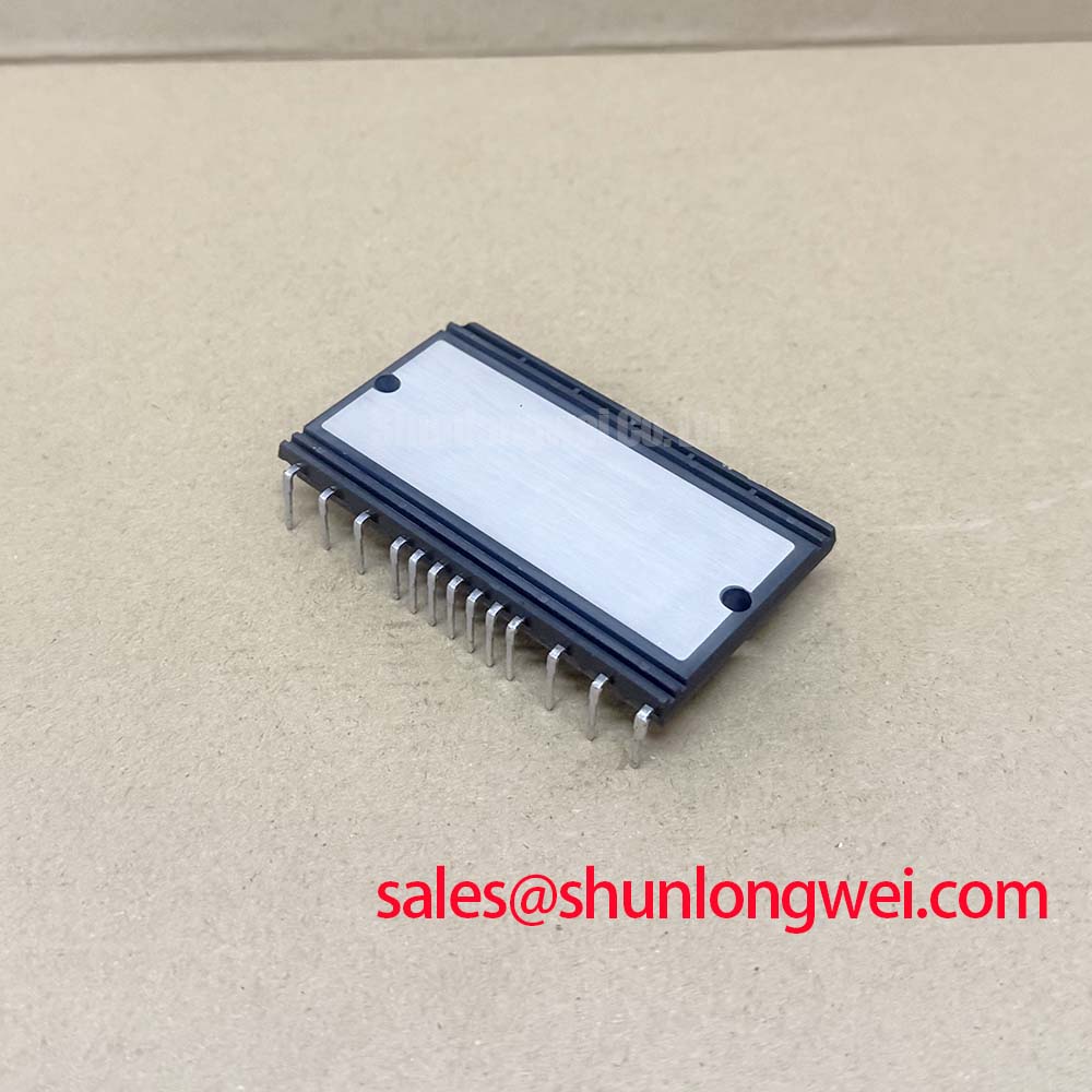
One of the most vital metrics for system longevity is the junction-to-case thermal resistance ($R_{th(j-c)}$). To understand its importance, imagine thermal resistance as the diameter of a drainage pipe; a lower resistance value (wider pipe) allows heat to flow away from the silicon die much faster, preventing the temperature from backing up and damaging the device. The CP30TD1-12Y utilizes an isolated copper baseplate that optimizes this path, allowing the module to maintain stable operation even in environments with limited airflow.
Optimized Application Scenarios
The highly integrated nature of the CP30TD1-12Y makes it particularly effective in the following scenarios:
- AC Motor Variable Frequency Drives (VFDs): The 600V rating is ideal for small to medium-sized industrial motors requiring precise speed control and high efficiency.
- Servo Drive Systems: The integrated brake chopper allows for safe handling of regenerative energy during rapid deceleration phases, essential for high-dynamic motion control.
- General Purpose Inverters: Simplifies the transition from PIM vs discrete designs, reducing assembly time and component count for UPS and solar inverter subsystems.
Best Match: Industrial designers seeking to minimize PCB dimensions in 2.2kW motor controllers will find the CP30TD1-12Y an ideal consolidated power solution.
Key Electrical and Thermal Specifications
| Parameter Category | Specific Rating / Characteristic | Value (Typical/Max) |
|---|---|---|
| Absolute Maximums | Collector-Emitter Voltage ($V_{CES}$) | 600V |
| Electrical Characteristics | Collector-Emitter Saturation Voltage ($V_{CE(sat)}$) | 2.1V (Max) |
| Switching Specs | Turn-off Delay Time ($t_{d(off)}$) | 350 ns |
| Thermal Properties | IGBT Thermal Resistance ($R_{th(j-c)}$) | 1.3 K/W |
| Isolation | Case Isolation Voltage | 2500V AC |
Engineer FAQ: Design and Integration
1. What is the recommended dead time for the CP30TD1-12Y?
Based on the switching characteristics in the data manual, a minimum dead time of 2.0µs to 2.5µs is typically recommended to prevent shoot-through currents in the inverter bridge, accounting for temperature-induced gate drive delays.
2. How should the module be mounted to ensure optimal thermal performance?
Heatsink flatness is critical for IGBT thermal design. The surface must be flat within 50µm, and a thin, uniform layer of high-performance thermal grease (approx. 100µm to 200µm) must be applied to eliminate air gaps.
3. Can the integrated NTC thermistor be used for direct gate drive control?
No. The NTC thermistor is intended for temperature monitoring via an external controller. It should be used as an input for the system’s MCU to trigger thermal protection loops, rather than directly driving semiconductor gates.
The CP30TD1-12Y represents a balanced approach to power density and reliability. By integrating multiple power functions into a single TD-package, it provides engineers with a verifiable path toward reducing system complexity without compromising the ruggedness required for industrial environments. Careful attention to thermal mounting and dead-time configuration allows this module to serve as the efficient core of modern AC drive systems.