Technical Overview of the Fuji Electric 7MBR100VX120-51 1200V 100A PIM IGBT Module
Fuji Electric 7MBR100VX120-51 1200V 100A PIM IGBT Module
Introduction and Core Product Highlights
The Fuji Electric 7MBR100VX120-51 is a highly integrated Power Integrated Module (PIM) optimized for space efficiency and thermal management in motor drive topologies. By consolidating converter, brake, and inverter stages alongside an integrated NTC thermistor into a single package, this module simplifies complex system layouts.
- Core Electrical Ratings: 1200V collector-emitter voltage, 100A continuous collector current, and a typical saturation voltage ($V_{CE(sat)}$) of 1.70V at a junction temperature of 25°C.
- Design Value: Lower stray inductance via optimized internal terminal routing and reduced total heatsink footprint.
This design answers a common engineering challenge: how to minimize inverter system volume while maintaining reliable thermal tracking and short-circuit capability.
Download Official Fuji Power Modules Catalog (PDF)
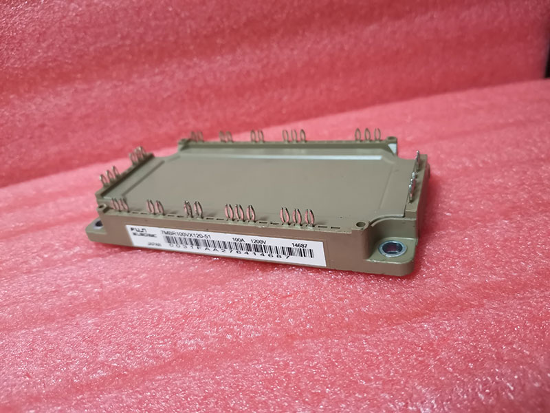
Technical Analysis: V-Series Trench Technology and Thermal Dynamics
The performance of the 7MBR100VX120-51 is driven by Fuji Electric’s V-Series trench-gate technology. Thin-wafer processing reduces conduction losses by lowering $V_{CE(sat)}$ to 1.70V under nominal current. Consequently, this minimized forward voltage drop diminishes static power losses, especially during continuous operations under high load currents.
Thermal resistance from junction to case ($R_{th(j-c)}$) is restricted to 0.25 K/W for the inverter IGBTs. You can imagine thermal resistance as a highway’s bottleneck; a lower resistance rating allows heat energy to flow more freely from the silicon chip to the copper baseplate. This prevents localized heat buildup, keeping junction temperatures safely below the 150°C continuous limit.
Additionally, the direct bond copper (DBC) substrate provides high isolation voltage of AC 2500V for one minute. This packaging choice ensures safe electrical isolation from the heatsink, mitigating parasitic capacitance and common-mode noise issues. Designers can route gate connections with lower loop inductance, achieving cleaner turn-on waveforms.
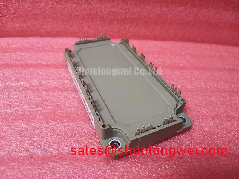
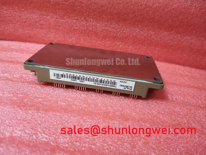
Optimized Application Scenarios
- Variable Frequency Drives (VFDs): The module’s integrated 3-phase input rectifier and brake chopper stage save board space in commercial motor drives.
- Industrial Servo Systems: High switching speeds enable carrier frequencies above 10 kHz, ensuring accurate current control loop performance. You can find more information about switching dynamics in the power semiconductors category.
- Industrial Power Supplies (UPS): Symmetrical layout limits voltage overshoot during turn-off, protecting sensitive converter components.
Best match: High-density industrial motor controllers requiring up to 100A continuous output current under single-heatsink mounting constraints.
7MBR100VX120-51 Key Technical Specifications
| Specification Parameter | Test Conditions / Section | Rated Value |
|---|---|---|
| Collector-Emitter Voltage ($V_{CES}$) | $T_j = 25^circ C$, Inverter Stage | 1200 V |
| Continuous Collector Current ($I_C$) | $T_C = 80^circ C$ | 100 A |
| Collector-Emitter Saturation Voltage ($V_{CE(sat)}$) | $I_C = 100 A, T_j = 25^circ C$ | 1.70 V (Typical) |
| Gate-Emitter Voltage ($V_{GES}$) | Continuous Rating | ±20 V |
| Max. Operating Junction Temperature ($T_{j(op)}$) | Continuous Operation | 150 °C |
| Thermal Resistance ($R_{th(j-c)}$) | IGBT Element (Inverter) | 0.25 K/W |
| Isolation Voltage ($V_{isol}$) | AC 1 Minute, 50/60Hz | 2500 V |
Engineering FAQ
Q: What is the main design advantage of using the 7MBR100VX120-51 over discrete IGBTs?
A: The module houses the input rectifier, brake chopper, and 3-phase inverter in a single package. This layout significantly reduces PCB trace routing inductance, assembly time, and thermal design complexity.
Q: How does the integrated NTC thermistor assist in module protection?
A: The thermistor monitors the baseplate temperature in close proximity to the silicon dies. This allows the system controller to initiate derating or shutdown before the chips reach destructive temperature levels. For analysis of overload conditions, see IGBT failures and root causes.
Q: What are the gate drive recommendations for avoiding parasitic turn-on?
A: It is recommended to use active Miller clamping or apply a negative gate bias voltage between -5V and -15V during the off-state to neutralize displacement currents flowing through the collector-gate capacitance.
System Integration and Design Goals
The 7MBR100VX120-51 PIM offers a balanced combination of low conduction losses and robust insulation characteristics. Its integrated layout helps hardware designers meet target efficiency rates in compact industrial enclosures while simplifying overall system assembly.