Toshiba MG150Q2YS1: A Robust IGBT for High-Power Industrial Applications
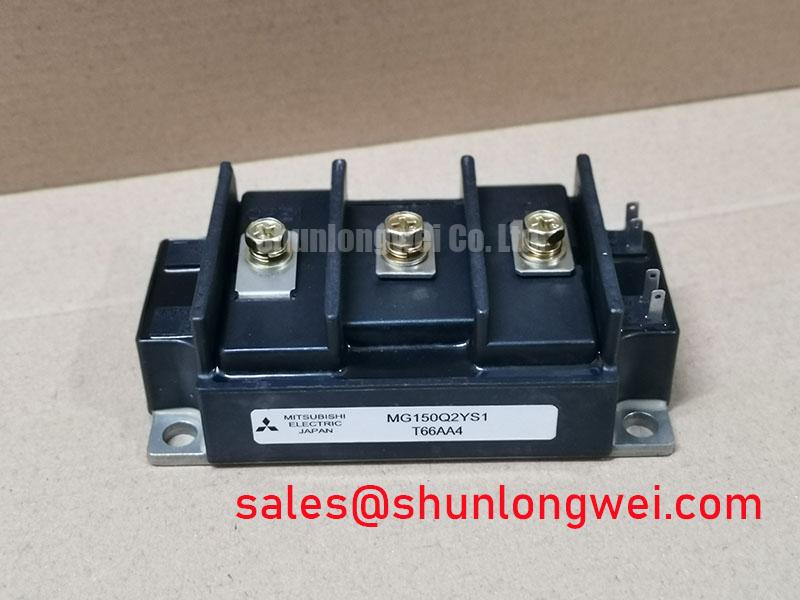
Toshiba MG150Q2YS1 1200V/150A IGBT Module
Engineered for High-Power Industrial Conversion
The Toshiba MG150Q2YS1 is a high-power IGBT module providing a robust and field-proven solution for demanding industrial power conversion systems. This module integrates a half-bridge configuration (two IGBTs) into a single, industry-standard package, simplifying the design of high-power inverters and motor drives. Its primary value proposition is delivering a balance of substantial power handling capability and reliable switching performance, making it a dependable choice for systems where longevity and consistent operation are critical design criteria.
- Core Specifications: 1200V | 150A | VCE(sat) (typ) 2.7V
- Key Strengths: High isolation voltage for operational safety, low thermal resistance for effective cooling.
- Design Focus: Optimized for moderate frequency applications requiring high durability.
Download A Reference Datasheet (PDF)

Technical Analysis for System Integration
The engineering value of the MG150Q2YS1 is found in its datasheet-verified performance metrics that ensure predictable behavior in real-world applications. The collector-emitter saturation voltage (VCE(sat)) is specified at a typical value of 2.7V at its nominal 150A collector current. This parameter is a direct indicator of conduction losses; a lower VCE(sat) results in less power dissipated as heat while the device is active. This directly contributes to higher overall system efficiency and can reduce the complexity of the required thermal management solution.
Furthermore, the module’s thermal resistance from junction to case (Rth(j-c)) is documented at 0.16°C/W per IGBT. This value can be thought of like the width of a pipe for heat to escape; a lower thermal resistance signifies a wider pipe, allowing heat to be transferred away from the active semiconductor junction to the heatsink more efficiently. This characteristic is fundamental for calculating cooling requirements and ensuring the device operates within its safe temperature limits, which is a core aspect of reliable IGBT thermal design.


Optimized Application Scenarios
The MG150Q2YS1 is well-suited for a range of high-power industrial applications where a balance of performance and robustness is key. Its specifications make it a strong candidate for:
- Variable Frequency Drives (VFDs): The 1200V/150A rating is ideal for controlling AC motors in the multi-kilowatt range, commonly found in industrial automation.
- Uninterruptible Power Supplies (UPS): Its proven reliability is essential for commercial UPS systems where consistent power delivery during outages is non-negotiable.
- Welding Power Supplies: The module’s capacity to handle high-current, pulsed loads ensures precise control of the welding arc in industrial equipment.
- Solar and Wind Inverters: In renewable energy systems, the high voltage rating provides the necessary margin for efficient DC-to-AC power conversion.
This module is an excellent match for systems operating at moderate switching frequencies where durability and straightforward thermal management are primary design considerations.
Key Specifications of the MG150Q2YS1
| Absolute Maximum Ratings (Tc=25°C unless otherwise specified) | |
|---|---|
| Collector-Emitter Voltage (VCES) | 1200 V |
| Gate-Emitter Voltage (VGES) | ±20 V |
| Collector Current (DC, @ Tc=80°C) (IC) | 150 A |
| Collector Power Dissipation (PC) | 780 W |
| Operating Junction Temperature (Tj) | -40 to +150 °C |
| Electrical & Thermal Characteristics | |
| Collector-Emitter Saturation Voltage (VCE(sat)) @ 150A | 2.7 V (Typ) |
| Thermal Resistance (Rth(j-c)) per IGBT | 0.16 °C/W |
| Isolation Voltage (Visol) (AC, 1 min.) | 2500 V |
Engineer’s FAQ
1. How is thermal resistance used in heatsink selection for the MG150Q2YS1?
To select a heatsink, first calculate the total power dissipation (P_total) based on conduction and switching losses in your application. Then, use the module’s thermal resistance (Rth(j-c) = 0.16°C/W) and the maximum allowable junction temperature (Tj_max = 150°C) to determine the required heatsink-to-ambient thermal resistance (Rth(s-a)). The formula is: Rth(s-a) ≤ (Tj_max – Ta_max) / P_total – Rth(j-c) – Rth(c-s), where Ta_max is the maximum ambient temperature and Rth(c-s) is the thermal interface material resistance.
2. What are the recommended mounting torque values for this module?
Proper mounting torque is crucial for ensuring low thermal resistance and mechanical reliability. According to the datasheet, the recommended torque for the main terminal screws is 3.5 – 4.5 N·m, and for the mounting screws, it is also 3.5 – 4.5 N·m. Applying incorrect torque can lead to poor thermal contact or physical damage to the module’s substrate.
3. Does the MG150Q2YS1 contain an integrated freewheeling diode?
Yes, the internal circuit diagram in the datasheet confirms that each IGBT within the half-bridge configuration is paired with a co-packaged freewheeling diode (FWD). This is essential for inductive load applications like motor drives, as it provides a path for current to flow when the IGBT is switched off.
4. What is the benefit of the 2500V isolation voltage?
The 2500V AC (for 1 minute) isolation rating provides a robust safety barrier between the high-voltage power circuit and the earthed heatsink/chassis. This is critical for meeting safety standards like UL and IEC in industrial equipment, protecting both operators and control electronics from high voltage potentials. For further reading on this topic, consider resources on the role of isolated baseplates in IGBT reliability.
Enabling Reliable Power System Design
The Toshiba MG150Q2YS1 provides a solid foundation for industrial power electronics. By delivering a well-documented and balanced set of performance characteristics, it allows engineers to design power conversion systems with predictable thermal behavior and operational durability. Its construction and ratings are tailored for long-service-life applications where reliability is the most important metric.