Toshiba MIG50J7CSB1W 600V 50A Intelligent Power Module: Overview and Technical Specifications
Toshiba MIG50J7CSB1W 600V 50A Intelligent Power Module
Introduction and Core Highlights
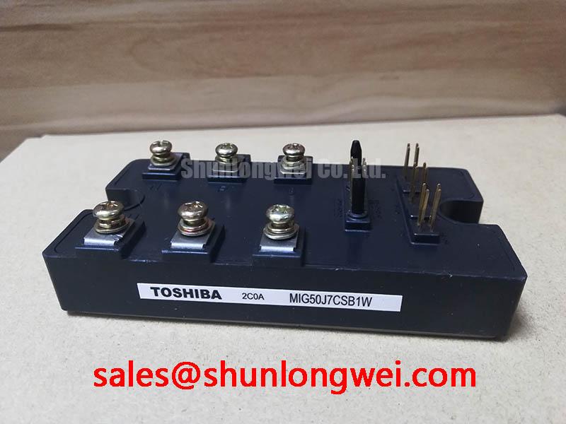
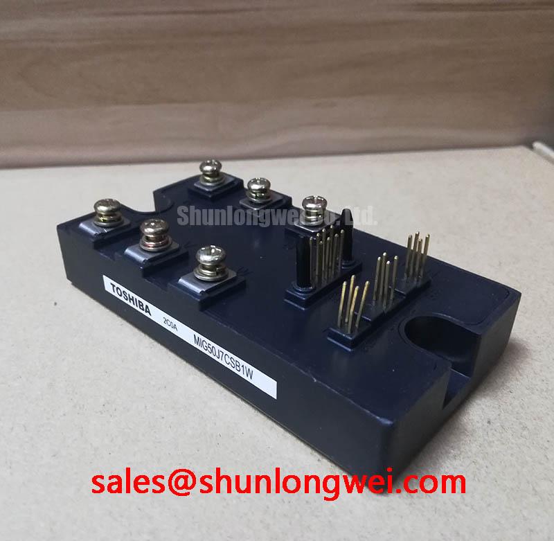
The Toshiba MIG50J7CSB1W is an N-channel silicon IGBT intelligent power module (IPM) designed for three-phase inverter applications. By integrating a high-performance six-pack IGBT bridge with dedicated gate drive circuitry, this module delivers robust power conversion within a compact footprint. It features a collector-emitter rating of 600V and a continuous collector current of 50A. Its built-in under-voltage lockout protection, overcurrent detection, and thermal shutdown functions shield the power stage from electrical stress. This module is widely sourced for industrial power semiconductors applications due to its high integration.
- Core Specifications: 600V | 50A | VCE(sat) 2.0V
- Key Engineering Advantages: Reduced system footprint via integrated drive logic; advanced fault detection with dedicated error output signaling.
Download Official Datasheet (PDF)

Technical Analysis Around Integrated Protection
The core engineering value of the MIG50J7CSB1W lies in the integrated structure of Intelligent Power Modules. In discrete designs, matching gate drivers to IGBTs requires careful routing to limit loop inductance, which often leads to parasitic turn-on. The MIG50J7CSB1W eliminates this by embedding the level-shifting gate drive inside the housing. By co-packaging the control IC and power switches, gate loop path length is virtually zero, keeping noise margin high.
Thermal performance is managed via an isolated copper baseplate. The junction-to-case thermal resistance ($R_{th(j-c)}$) is specified at $1.25,^circtext{C/W}$ for the IGBT portion. Think of thermal resistance as a bottleneck in a water pipe. A lower resistance value means thermal energy flows more rapidly from the silicon junction to the heatsink. This prevents localized hotspots and ensures the module remains within its safe operating temperature range during continuous full-load switching.
Additionally, the module handles overcurrent (OC) events autonomously. If the collector current exceeds the trip threshold (typically $80text{A}$), the internal control circuit soft-shuts down the gate drive and triggers the fault output ($F_O$) line. This hardware-level protection operates independently of the master microcontroller’s clock cycles, preventing catastrophic thermal runaway during short circuits.
Optimized Application Scenarios
- Variable Frequency Drives (VFDs): The 600V rating accommodates standard 220V/240V AC input rectification with sufficient safety margin against DC bus voltage spikes.
- Industrial AC Servo Motors: Precise gate timing matched with low internal delay times ($t_{off} approx 2.0,mutext{s}$) allows high-frequency PWM switching for smooth torque control.
- Uninterruptible Power Supplies (UPS): Active filtering and low conduction loss profiles ensure efficient energy delivery during battery discharge cycles.
The MIG50J7CSB1W is a robust match for industrial motor drives requiring integrated diagnostics and compact three-phase power inversion.
Key Specifications Parameter Table
| Parameter Category | Specification Description | Official Value |
|---|---|---|
| Absolute Maximum Ratings | Collector-Emitter Voltage (VCES) | 600 V |
| Collector Current (IC @ Tc = 25°C) | 50 A | |
| Junction Temperature (Tj) | -20°C to +150°C | |
| Electrical Characteristics (Tj = 25°C) | Collector-Emitter Saturation Voltage VCE(sat) (typ.) | 2.0 V (IC = 50A, VIN = 15V) |
| Collector Cut-off Current ICES (max.) | 1.0 mA (VCE = 600V) | |
| Overcurrent Trip Level (OC) | Min: 75 A / Typ: 100 A | |
| Thermal & Mechanical | Junction-to-Case Thermal Resistance Rth(j-c) (IGBT) | 1.25 °C/W |
| Isolation Voltage (Visol) | 2500 V RMS (AC, 1 minute) |
Engineer FAQ
How does the MIG50J7CSB1W handle under-voltage conditions on the control power supply?
The module features an internal under-voltage detection circuit. If the control voltage ($V_{D}$) drops below the trip level (typically $12.0text{V}$), the gate drive turns off the IGBTs, preventing incomplete switching that could cause excessive dissipation. Operation resumes when $V_{D}$ rises above the reset level (typically $12.5text{V}$).
What is the function of the fault output ($F_O$) pin on the MIG50J7CSB1W?
The $F_O$ terminal outputs a low-level signal to the host controller when overcurrent, control under-voltage, or heatsink over-temperature conditions are detected. The duration of this fault signal is determined by an external capacitor connected to the control port.
How does the thermal performance of this module compare to other variants, such as the Toshiba MIG50Q7CSAOX IGBT module?
The MIG50J7CSB1W utilizes a different packaging structure and internal layout. Designers must calculate thermal paths using the specific $R_{th(j-c)}$ value of $1.25,^circtext{C/W}$ for the IGBT and $2.00,^circtext{C/W}$ for the diode, ensuring the case temperature ($T_c$) remains within the safe operating envelope.
Design Integration and Performance Focus
By combining a six-channel power stage with onboard drive logic and real-time error reporting, the MIG50J7CSB1W enables engineers to implement space-efficient three-phase inverter designs. The module’s built-in protections eliminate external gate drive components, maintaining signal integrity and power efficiency across high-current load transitions.