Technical Analysis of the Fuji Electric 6DI120C-060 Darlington Transistor Module
Fuji Electric 6DI120C-060 Darlington Transistor Module
Introduction and Core Technical Highlights
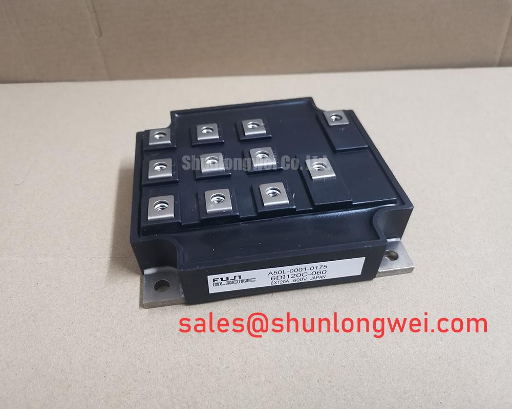
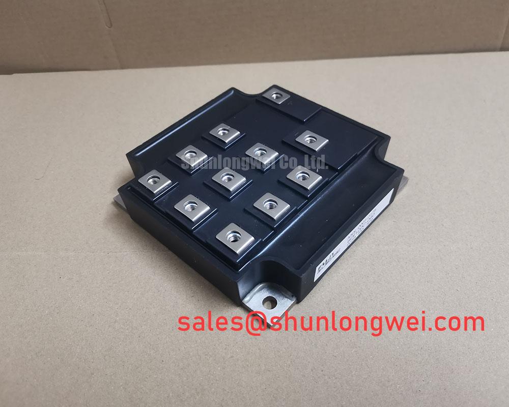
The 6DI120C-060 is a 600V, 120A power transistor module manufactured by Fuji Electric. It integrates six Darlington transistors in a three-phase bridge configuration, complete with fast recovery antiparallel free-wheeling diodes. This layout simplifies drive circuitry and mechanical integration by housing a complete inverter stage in a single, electrically isolated package.
- Core Ratings: 600V Collector-Emitter Voltage | 120A Continuous Collector Current | 6-in-1 Bridge Topology
- Engineering Benefits: Eliminates discrete component mounting layout challenges and reduces loop parasitic inductance.
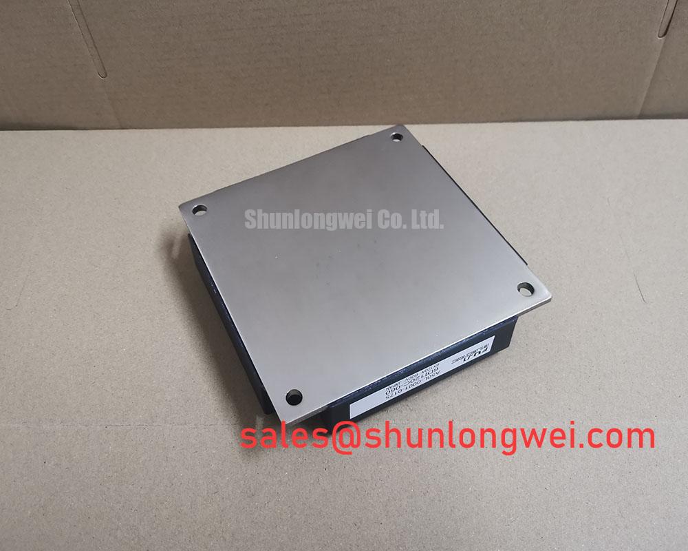
- Thermal Management: Incorporates a copper baseplate with high-insulation ceramic substrate for direct heatsink assembly.
Request Datasheet and Technical PDF

Technical Analysis and Unique Value Proposition
The 6DI120C-060 utilizes high DC current gain ($h_{FE}$) Darlington pairs to reduce the base drive current requirements. This integration allows low-power control circuitry to switch high-current loads without complex multi-stage pre-driver circuits. Designers can implement simpler gate drivers, which improves noise immunity in environments prone to electromagnetic interference (EMI).
Thermal dissipation is managed through the module’s physical construction. The internal ceramic substrate acts as an electrical insulator while maintaining low thermal resistance ($R_{th(j-c)}$). Think of thermal resistance like a thermal bottleneck; a lower value behaves like a wider highway, allowing heat to escape rapidly from the silicon junction to the heatsink to prevent thermal runaway. This design utilizes an isolated baseplate to safely isolate electrical potentials from the chassis ground.

For smaller system footprints, engineers often reference the Fuji 6DI30B-050 module. For configurations requiring different switching profiles, the Fuji Electric 6DI120D-060 offers a comparable alternative. Integrating the free-wheeling diodes directly adjacent to the transistor dies minimizes the inductive loop, clamping reverse voltage spikes during inductive load turn-off phases.
Optimized Application Scenarios
- AC Motor Drives: The three-phase configuration serves as the output inverter stage in standard variable frequency drives.
- Uninterruptible Power Supplies (UPS): Used in the inverter section to generate stable sinusoidal AC outputs from DC battery banks.
- DC Chopper Controls: Suitable for DC motor speed controllers requiring fast switching speeds and robust overcurrent tolerances.
- Industrial Welding Systems: Provides stable switching stages in high-current welding power converters.
Best match for legacy industrial motor controllers requiring high DC current gain and direct three-phase integration in a single housing.
Key Specifications Table
| Absolute Maximum Ratings & Electrical Characteristics (at $T_c = 25^circtext{C}$ unless specified) | ||
|---|---|---|
| Collector-Emitter Voltage ($V_{CES}$) | 600 V | Maximum blocking voltage across collector-emitter |
| Collector Current ($I_C$) | 120 A | Continuous DC collector current capability |
| Collector Current Peak ($I_{CP}$) | 240 A | Pulse limit (1 ms width) |
| Collector Power Dissipation ($P_C$) | 450 W | Maximum power dissipation per transistor element |
| Base Current ($I_B$) | 7 A | Continuous drive base current |
| Isolation Voltage ($V_{isol}$) | 2500 V | AC 1 minute baseplate-to-terminal dielectric strength |
| Operating Junction Temperature ($T_j$) | +150 °C | Maximum permissible internal die temperature |
| DC Current Gain ($h_{FE}$) | 100 (Min) | Measured at $I_C = 120text{A}, V_{CE} = 5text{V}$ |
Engineer FAQ
How does the 6DI120C-060 simplify the design of base drive circuits?
Because it is a Darlington-connected power module, it possesses a high DC current gain ($h_{FE} ge 100$). This minimizes the input base drive current needed to fully saturate the transistor. As a result, engineers can use lower-power driver stages, reducing system footprint and cost.
What mounting torque is recommended for the power terminals and heatsink?
To avoid housing fractures and high contact resistance, specify a torque of 3.5 N·m for terminal connections and a mounting torque of 3.0 N·m to the heatsink. Consistent torque prevents micro-gaps that degrade thermal transfer.
How do the internal antiparallel diodes protect the module?
The integrated fast-recovery diodes act as freewheeling paths. When inductive loads (such as motor windings) switch off, the magnetic field collapses and generates a high-voltage spike. The diodes clamp this spike to the DC rail, preventing collector-emitter overvoltage breakdown.
The Fuji Electric 6DI120C-060 provides a robust, integrated power switching layout for legacy industrial converter maintenance and custom motor control configurations. By grouping six Darlington pairs into a single module, it reduces design complexity and assembly overhead.