Vishay T70HFL20S02: A 70A Fast Recovery Diode for Efficient Power Conversion
“`html
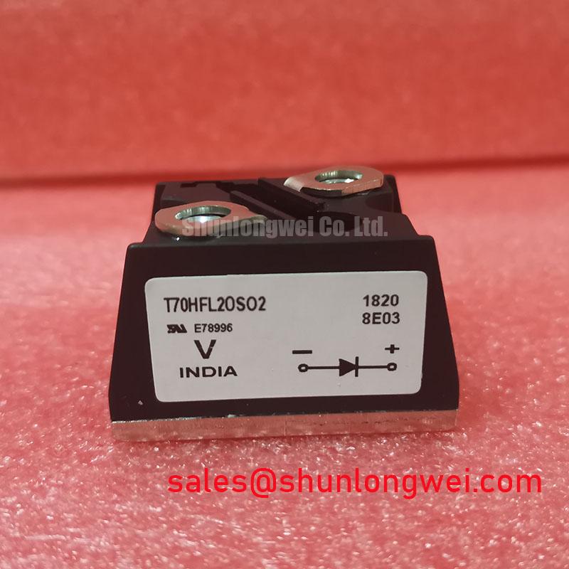
Vishay T70HFL20S02 Fast Recovery Diode, 200V 70A
High-Frequency Rectification with Superior Thermal Performance
The Vishay T70HFL20S02 is a fast recovery diode engineered for robust performance in high-frequency power conversion systems. Its primary value stems from a rapid reverse recovery time combined with an industry-standard stud-mount package, ensuring both electrical efficiency and effective thermal management. This diode is specifically built for applications demanding minimal switching losses and high reliability under substantial current loads.
- Core Specifications: 200V | 70A | 200 ns (t_rr)
- Key Advantages: Minimizes switching losses in high-frequency circuits, robust package simplifies thermal design.
- Engineered For: Efficient operation as a freewheeling diode or in output rectification stages.
Download the official T70HFL20S02 Datasheet (PDF)

Technical Analysis for System Optimization
A key performance metric of the T70HFL20S02 is its fast reverse recovery time (t_rr) of 200 ns. In high-frequency applications like switched-mode power supplies or inverters, a diode’s speed during the transition from forward conduction to reverse blocking is critical. A shorter t_rr directly reduces reverse recovery losses, a significant component of total switching losses. This reduction translates to higher overall system efficiency and less heat generated, allowing for more compact designs or operation at higher power levels without thermal compromise.
The device’s thermal design is anchored by its D-55 (T-Module) package. The thermal resistance from junction to case (RthJC) is a critical parameter for any power semiconductor. You can think of thermal resistance as the width of a pipe for heat; a lower value means heat can escape more easily. The T70HFL20S02’s stud-mount configuration provides a low-resistance thermal path directly from the semiconductor junction to the heatsink, which is essential for maintaining a safe operating temperature and ensuring long-term reliability, especially when handling its maximum average forward current of 70A.


Optimized Application Scenarios
The electrical and thermal characteristics of the T70HFL20S02 make it highly suitable for specific, demanding applications:
- Freewheeling Diodes: When used in conjunction with thyristors or as a freewheeling diode in motor control circuits, its fast recovery protects the switching device and minimizes energy loss during commutation.
- High-Frequency Welders: The low switching losses are essential for the efficiency of modern inverter-based welding power supplies.
- DC Choppers and Switched-Mode Power Supplies (SMPS): Its speed and current handling capability are ideal for output rectification stages where efficiency is paramount.
- Inductive Heating: The device can reliably handle the high-frequency currents and reactive power present in resonant inductive heating circuits.
This diode is an optimal match for industrial power conversion systems requiring efficient rectification of up to 70A at high frequencies.
Key Specifications of the T70HFL20S02
| Absolute Maximum Ratings | |
|---|---|
| Repetitive Peak Reverse Voltage (V_RRM) | 200 V |
| Average Forward Current (I_F(AV)) @ T_C = 87 °C | 70 A |
| Non-Repetitive Surge Current (I_FSM) @ 50 Hz | 870 A |
| Operating Junction Temperature Range (T_J) | -40 °C to 125 °C |
| Electrical & Thermal Characteristics | |
| Max. Forward Voltage (V_FM) @ 220 A, T_J = 25 °C | 1.73 V |
| Reverse Recovery Time (t_rr), typical | 200 ns |
| Max. Reverse Current (I_RRM) @ T_J = 125 °C | 15 mA |
| Thermal Resistance, Junction to Case (R_thJC) | 0.45 °C/W |
| Mounting Torque | 2.3 to 3.4 Nm (20 to 30 lbf·in) |
Engineer’s FAQ
1. What makes the T70HFL20S02 a “fast recovery” diode?
Its designation as a fast recovery diode is based on its reverse recovery time (t_rr) of approximately 200 nanoseconds. This rapid switching capability from a conducting to a non-conducting state is critical for minimizing power loss in circuits that operate at high frequencies, such as those found in power semiconductors for inverters and DC-DC converters.
2. What is the correct mounting procedure to ensure optimal cooling?
For effective thermal management, the base of the module should be mounted to a clean, flat heatsink surface with a thin layer of thermal compound. The datasheet specifies a mounting torque of 2.3 Nm to 3.4 Nm (20 to 30 lbf·in). Applying the correct torque is critical to minimize the thermal resistance between the device case and the heatsink without causing mechanical stress to the package.
3. How does the electrically isolated baseplate benefit my design?
The D-55 package features an electrically isolated baseplate with an isolation voltage of 3500 V_RMS. This allows multiple modules to be mounted on a single, common heatsink without needing separate insulating pads for each device. This simplifies mechanical assembly, reduces component count, and can lead to a more compact and cost-effective overall system design. Explore more about the foundation of high-voltage reliability.
Enabling Efficient Power Conversion
The T70HFL20S02 provides a well-defined solution for engineers developing high-current, high-frequency systems. Its blend of rapid switching, high current capacity, and thermally efficient packaging allows for the design of reliable and compact power stages. This device directly supports the goals of improving system efficiency and ensuring robust operation under demanding industrial conditions.