VBO125-12N07 Rectifier Module: A Deep Dive into Performance and Applications
VBO125-12N07 | 1200V 124A Single Phase Rectifier Module
Introduction and Core Highlights
The IXYS VBO125-12N07 is a single-phase rectifier bridge module engineered for robust performance in high-power applications. Its primary value lies in its combination of a high current rating and excellent thermal efficiency within a compact, isolated package. This component simplifies the front-end design of power conversion systems by providing a reliable, off-the-shelf rectification solution. It is built with planar passivated chips which contribute to low forward voltage drop and improved temperature cycling capability.
- Core Specifications: 1200V VRRM | 124A IdAVM | 1.8kA IFSM
- Key Advantages: Features an isolated baseplate for simplified thermal mounting and offers significant space and weight savings compared to discrete solutions.
This module directly addresses the need for efficient and durable power rectification in demanding industrial environments. For detailed specifications, you can download the official datasheet (PDF).

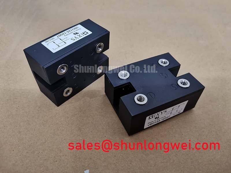

Technical Analysis
The engineering value of the VBO125-12N07 is rooted in its electrical robustness and thermal design. The module’s use of planar passivated chips ensures a low forward voltage drop (VF) of typically less than 1.3V at 150A, which directly translates to lower conduction losses and reduced heat generation during operation. This is a critical factor in power systems, as lower losses improve overall system efficiency and reduce the burden on cooling systems. For further reading on power device losses, see our analysis of the quest for lower VCE(sat) in modern transistors.
Furthermore, the module’s thermal resistance from junction to case (RthJC) is specified at 0.138 K/W for the entire module. This parameter can be compared to the width of a pipe for heat dissipation; a lower value signifies a wider pipe, allowing heat to escape more easily from the active silicon to the heatsink. This efficient heat transfer, combined with a maximum operating junction temperature of 150°C, provides substantial thermal headroom for reliability in demanding industrial load cycles. Effective thermal management is a cornerstone of reliable system design.
Optimized Application Scenarios
The VBO125-12N07 is specified for a range of high-power rectification tasks. Its characteristics make it particularly suitable for the following:
- Input Rectifiers for PWM Inverters: The high blocking voltage of 1200V and surge current capability (up to 1.8kA) make it ideal for the front-end of Variable Frequency Drives (VFDs).
- Supplies for DC Power Equipment: With a continuous average forward current of 124A, it can serve as the main rectifier in robust industrial DC power supplies.
- Battery DC Power Supplies: Its low forward voltage drop contributes to higher efficiency in high-current battery charging systems.
- Field Supply for DC Motors: Provides a simple and reliable solution for generating the field excitation voltage required by large DC motors.
This module is an optimal match for industrial power conversion systems operating from 230V to 480V AC mains, where reliability and thermal performance are critical.
Key Specification Parameters
| Parameter | Symbol | Conditions | Value | Unit |
|---|---|---|---|---|
| Absolute Maximum Ratings | ||||
| Repetitive Peak Reverse Voltage | VRRM | 1200 | V | |
| Average Forward Current | IdAVM | TC = 85°C, module | 124 | A |
| Peak Forward Surge Current | IFSM | TVJ = 45°C, t = 10 ms (50 Hz) | 1800 | A |
| Operating Junction Temperature | TVJ | -40 to +150 | °C | |
| Electrical & Thermal Characteristics | ||||
| Forward Voltage | VF | IF = 150 A, TVJ = 25°C | ≤ 1.3 | V |
| Reverse Current | IR | VR = VRRM, TVJ = 150°C | ≤ 8.0 | mA |
| Thermal Resistance, Junction to Case | RthJC | Per module | 0.138 | K/W |
| Isolation Voltage | VISOL | 50/60 Hz, RMS, t = 1 min | 2500 | V~ |
Note: All specifications are sourced directly from the manufacturer’s datasheet. Characterisitcs can vary, and the linked datasheet should be consulted for definitive values.
Engineer’s FAQ
- What are the key considerations for mounting the VBO125-12N07 to a heatsink?
- To ensure effective cooling, the heatsink surface should be flat and clean. Apply a thin, uniform layer of thermal grease before mounting. The datasheet specifies a mounting torque of 5 ± 15% Nm for the M5 screws to achieve optimal thermal contact without inducing mechanical stress on the module’s baseplate.
- How do I calculate the heatsink requirement for this module?
- First, calculate the total power dissipation (PD) based on the forward voltage drop (VF) and average current (IAV) in your application. Then, use the module’s RthJC (0.138 K/W) to find the maximum allowable case-to-ambient thermal resistance (RthCA) with the formula: RthCA = (TJmax – TA)/PD – RthJC. Your chosen heatsink’s thermal resistance (RthSA) must be lower than this calculated RthCA value.
- Is the baseplate electrically isolated?
- Yes. The VBO125-12N07 features an isolated baseplate with an isolation voltage rating of 2500 V~ (for 1 minute), which simplifies mounting onto a grounded chassis or a common heatsink shared with other components, reducing assembly complexity and potential shock hazards.
Enabling Robust Power Designs
The VBO125-12N07 from IXYS provides the essential building block for reliable and efficient AC-to-DC power conversion. Its integration of a high-current rectifier in a thermally proficient, isolated package allows engineers to streamline the design of industrial-grade power systems, focusing on performance and long-term reliability without the complexity of discrete component layouts.