FZ2400R12KL4C: A Technical Review of a High-Current IGBT for Power Systems
FZ2400R12KL4C IGBT Module: High Current for Power Systems
Introduction and Core Highlights
The Infineon FZ2400R12KL4C is a high-power IGBT module featuring a chopper configuration, engineered for robust performance in demanding high-current applications. Its primary value lies in the combination of a very high current rating with proven IGBT technology, providing a dependable building block for power conversion systems. This module is structured to manage substantial power flow while maintaining operational stability.
- Core Specifications: 1200V | 2400A | VCE(sat) 1.7V (typ.)
- Key Advantages: Facilitates simplified high-power inverter designs, robust thermal performance.
For engineers designing systems such as high-power motor drives or large-scale inverters, the FZ2400R12KL4C offers a high-current capability that can reduce the need for complex paralleling of multiple smaller modules.
Download the Official FZ2400R12KL4C Datasheet (PDF)
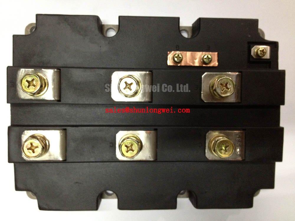
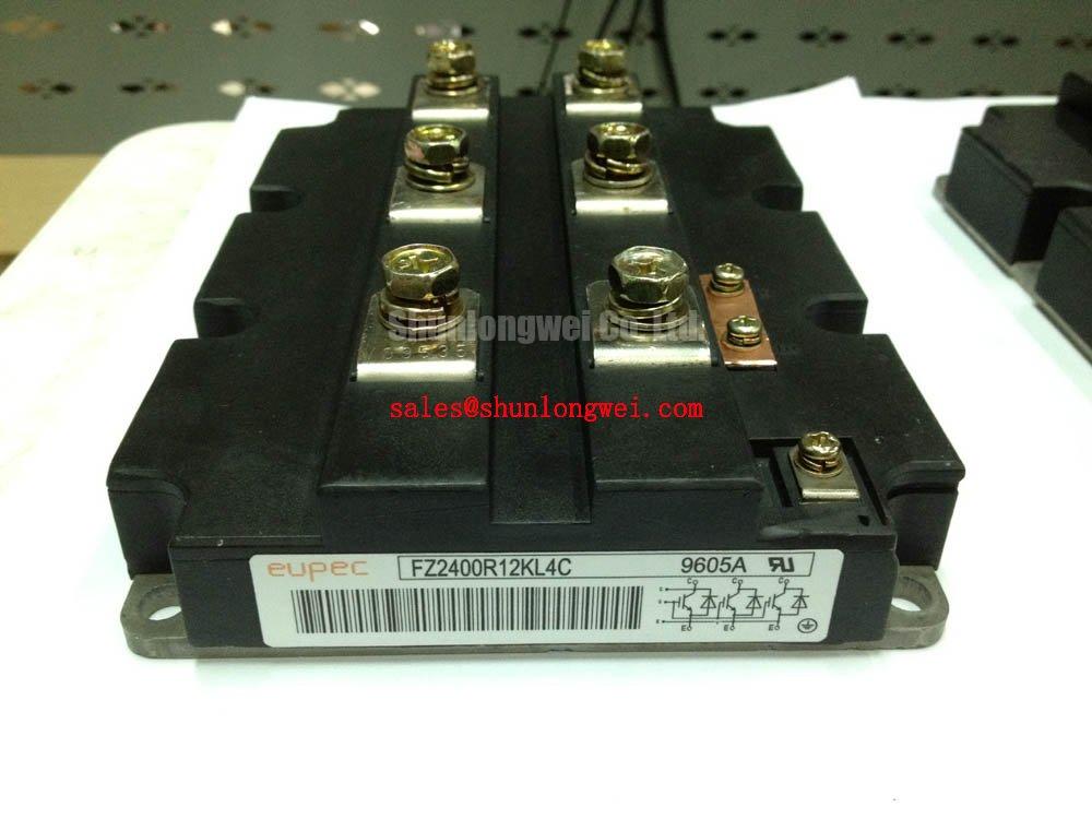
Technical Analysis for System Design
The engineering value of the FZ2400R12KL4C is rooted in its fundamental electrical and thermal characteristics. The nominal collector current (IC nom) of 2400A provides a massive power handling capacity. This high rating is central to its utility in applications like megawatt-class solar inverters and industrial motor drives, where high current is a primary design requirement.
A critical parameter for efficiency is the collector-emitter saturation voltage, VCE(sat). The datasheet specifies a typical VCE(sat) of 1.7V at the nominal current of 2400A (Tvj = 25°C). This value directly impacts conduction losses; a lower VCE(sat) results in less power dissipated as heat during operation. This improves overall system efficiency and simplifies the thermal management design. Think of thermal resistance (RthCH) as the width of a pipe for heat to escape; the specified 6.4 K/kW for the IGBT signifies an effective pathway for thermal dissipation from the housing to the heatsink.
The module’s IHM-B housing is designed for mechanical stability and effective thermal transfer. The specified isolation test voltage of 2.5 kV (RMS, 50 Hz, 1 min) confirms its suitability for systems where high-voltage isolation is a safety and operational necessity. Careful consideration of thermal management is essential to leverage the full capacity of this high-power device.
Optimized Application Scenarios
The FZ2400R12KL4C is specified for high-power conversion tasks where current demand is the primary challenge.
- High-Power Motor Drives: In large industrial motors for rolling mills or mining equipment, the 2400A capability allows for direct control of high-horsepower motors, often reducing the need for paralleling modules.
- Wind Turbines: The module’s high current rating makes it a strong candidate for the main inverter in multi-megawatt wind power generation systems, converting the generator’s output to grid-compatible AC power.
- Utility-Scale Solar Inverters: For central inverters that consolidate power from large solar arrays, the FZ2400R12KL4C can handle the high DC input currents, improving power density and system reliability.
- Industrial Welding: High-current welding power supplies can benefit from the module’s ability to deliver sustained high currents, ensuring stable arc performance.
This module is best matched for applications where maximizing current per package is critical for achieving power density and simplifying the overall mechanical design.
Key Specification Parameters
| Absolute Maximum Ratings (Tvj = 25°C unless otherwise specified) | ||
|---|---|---|
| Parameter | Symbol | Value |
| Collector-Emitter Voltage | VCES | 1200 V |
| Continuous DC Collector Current | IC nom | 2400 A |
| Repetitive Peak Collector Current (tP = 1 ms) | ICRM | 4800 A |
| Gate-Emitter Peak Voltage | VGES | ±20 V |
| Electrical & Thermal Characteristics | ||
| Collector-Emitter Saturation Voltage (IC=2400A, VGE=15V, Tvj=25°C) | VCE sat | 1.70 V (typ) |
| Gate Threshold Voltage (IC=96mA, VCE=VGE, Tvj=25°C) | VGE(th) | 5.8 V (typ) |
| Operating Junction Temperature | Tvj op | -40 to +125 °C |
| Thermal Resistance, Case to Heatsink (IGBT) | RthCH | 6.4 K/kW (typ) |
Engineer’s FAQ
Q: What is the main advantage of using a single FZ2400R12KL4C versus multiple lower-current IGBTs in parallel?
A: Using a single high-current module like the FZ2400R12KL4C simplifies the mechanical layout, ensures more uniform thermal distribution, and reduces the complexity of gate drive circuitry and current sharing balancing that is required when paralleling multiple devices. More information on IGBTs can be found in our power semiconductors category.
Q: What are the key mounting and thermal interface considerations for this module?
A: Due to its high power dissipation, proper mounting is critical. The datasheet specifies a mounting torque for the terminals and housing. A high-quality thermal interface material (TIM) must be applied evenly to the baseplate to minimize the thermal resistance to the heatsink (RthCH) and ensure effective cooling.
Q: How does the maximum operating junction temperature of 125°C impact the design?
A: The maximum operating junction temperature (Tvj op) of 125°C is a critical limit. The thermal design, including heatsink selection and airflow, must be engineered to keep the IGBT junction temperature below this rating under all operating conditions to ensure system reliability and prevent component failure.
Design Enablement
The FZ2400R12KL4C provides system designers with a high-current, single-package solution that helps streamline the development of powerful and efficient power conversion systems. Its combination of a 2400A rating and established IGBT technology enables the creation of more compact, reliable, and mechanically simpler high-power inverters and drives. For more on IGBT reliability, explore topics like the role of silicone gels in IGBT modules.