CM400DU-24NFH: A Technical Analysis of a High-Frequency IGBT Module
Mitsubishi CM400DU-24NFH: 1200V 400A Dual IGBT Module
Engineered for High-Frequency Power Conversion
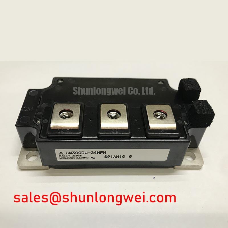
The Mitsubishi CM400DU-24NFH is a dual IGBT module designed for high-power, high-frequency switching applications. It integrates two IGBTs in a half-bridge configuration, providing a robust solution for power conversion systems. This module’s primary value proposition lies in its optimized design for low switching losses and efficient thermal management, enabling reliable performance in demanding industrial environments.
- Core Specifications: 1200V | 400A | VCE(sat) 5.0V (typ.)
- Key Advantages: Low power dissipation and suitability for high-frequency operation up to 60kHz.
- System Benefit: The integrated nature simplifies thermal management and system assembly.
For detailed electrical and thermal characteristics, download the official datasheet (PDF).

Technical Analysis for System Integration
A critical parameter for power system efficiency is the collector-emitter saturation voltage, VCE(sat). The CM400DU-24NFH specifies a typical VCE(sat) of 5.0V at its nominal 400A current. This value is a direct indicator of conduction loss; a lower VCE(sat) results in less power dissipated as heat during the on-state. Think of VCE(sat) as the resistance of a valve when it’s fully open. A lower resistance allows fluid (current) to pass through with less energy loss. This characteristic reduces the demand on the system’s cooling infrastructure, a key factor in thermal design explored in articles like mastering IGBT thermal design.
The module’s architecture contains two IGBTs and two free-wheeling diodes (FWDi) in a half-bridge circuit. This dual configuration is fundamental for creating the AC waveforms in inverters. Each component is electrically isolated from the baseplate, which simplifies mounting to a heatsink and improves overall system reliability by preventing accidental short circuits. The integrated super-fast recovery free-wheel diode is essential for handling the reverse recovery currents generated by inductive loads, such as electric motors.


Optimized Application Scenarios
The electrical and thermal specifications of the CM400DU-24NFH make it a suitable component for several high-power applications:
- Induction Heating & Power Supplies: The module is explicitly designed for high-frequency switching (30-60kHz), making it ideal for the resonant circuits found in modern induction heaters and switch-mode power supplies.
- Variable Frequency Drives (VFDs): Its 400A current rating and robust thermal performance provide the necessary power handling for controlling large industrial AC motors. The half-bridge configuration is a standard building block for three-phase inverters.
- Uninterruptible Power Supplies (UPS): In high-capacity UPS systems, efficiency is key to maximizing battery runtime. The module’s low conduction losses contribute directly to higher overall system efficiency.
- Welding Equipment: Inverter-based welders require precise and rapid control of high currents. The fast switching capability of the NFH series enables stable arc control for high-quality welds.
Its balance of high voltage, high current, and fast-switching capability makes it a strong candidate for high-power inverter and converter designs.
Key Specifications of the CM400DU-24NFH
| Parameter | Symbol | Value | Conditions |
|---|---|---|---|
| Absolute Maximum Ratings (Tj=25°C) | |||
| Collector-Emitter Voltage | VCES | 1200V | VGE = 0V |
| Collector Current (DC) | IC | 400A | – |
| Total Power Dissipation | Pc | 2080W | – |
| Isolation Voltage | Viso | 2500Vrms | AC 1 minute |
| Electrical Characteristics (Tj=25°C) | |||
| Collector-Emitter Saturation Voltage | VCE(sat) | 5.0V (typ) / 6.5V (max) | IC = 400A, VGE = 15V |
| Gate-Emitter Threshold Voltage | VGE(th) | 5.5V to 8.5V | IC = 40mA, VCE = 10V |
| Thermal Characteristics | |||
| Thermal Resistance (Junction to Case, IGBT) | Rth(j-c)Q | 0.06 K/W | Per 1/2 module |
| Operating Junction Temperature | Tj | -40 to +150°C | – |
Note: This table presents a selection of key parameters. Engineers must consult the official CM400DU-24NFH datasheet for complete specifications and performance curves.
Engineer’s FAQ
What is the primary benefit of the NFH-Series for high-frequency applications?
The NFH series is specifically engineered for reduced switching losses, particularly turn-off loss (Eoff). This allows the module to operate efficiently at higher frequencies (up to 60kHz) compared to standard IGBTs, enabling the use of smaller magnetic components and improving power density.
What are the critical mounting considerations for the CM400DU-24NFH?
Proper thermal contact is essential. The heatsink surface must be flat and clean. A uniform layer of thermal grease should be applied to achieve the specified thermal resistance. Mounting bolts must be tightened to the torque specified in the datasheet to ensure low thermal resistance without causing mechanical stress to the module’s isolated baseplate.
Does this module include short-circuit protection?
No, the datasheet for the CM400DU-24NFH explicitly states that “No short circuit capability is designed”. Therefore, the gate drive circuit and system-level controls must implement short-circuit detection and protection, a topic covered in resources like this guide to the I²t rating for IGBT protection.
What does the dual or “2-in-1” configuration mean?
It signifies that the package contains two IGBT transistors and two associated free-wheeling diodes, connected internally in a half-bridge topology. This is a fundamental building block for most power inverters and converters.
This module provides a validated, high-current switching solution that enables designers to build efficient and reliable power conversion systems. The focus on high-frequency performance allows for compact system designs without compromising on thermal stability.