FZ2400R17HP4_B29 IGBT Module: A Technical Analysis for High-Power Applications
FZ2400R17HP4_B29 IGBT Module | 1700V 2400A
Introduction and Core Highlights
The Infineon FZ2400R17HP4_B29 is a high-power IGBT module engineered for megawatt-scale power conversion systems. Its primary value is delivering extreme current handling and robust high-voltage operation by utilizing TRENCHSTOP™ IGBT4 and field stop technology. This combination enables exceptional thermal stability and low conduction losses, which are critical parameters when designing high-power industrial drives and renewable energy inverters. The module’s design allows for efficient heat dissipation, a key consideration for improving system reliability and power density in demanding applications.
- Core Specifications: 1700V | 2400A | Tvj op 150°C
- Key Advantages: High thermal headroom, Low conduction losses
Download the Official FZ2400R17HP4_B29 Datasheet (PDF)
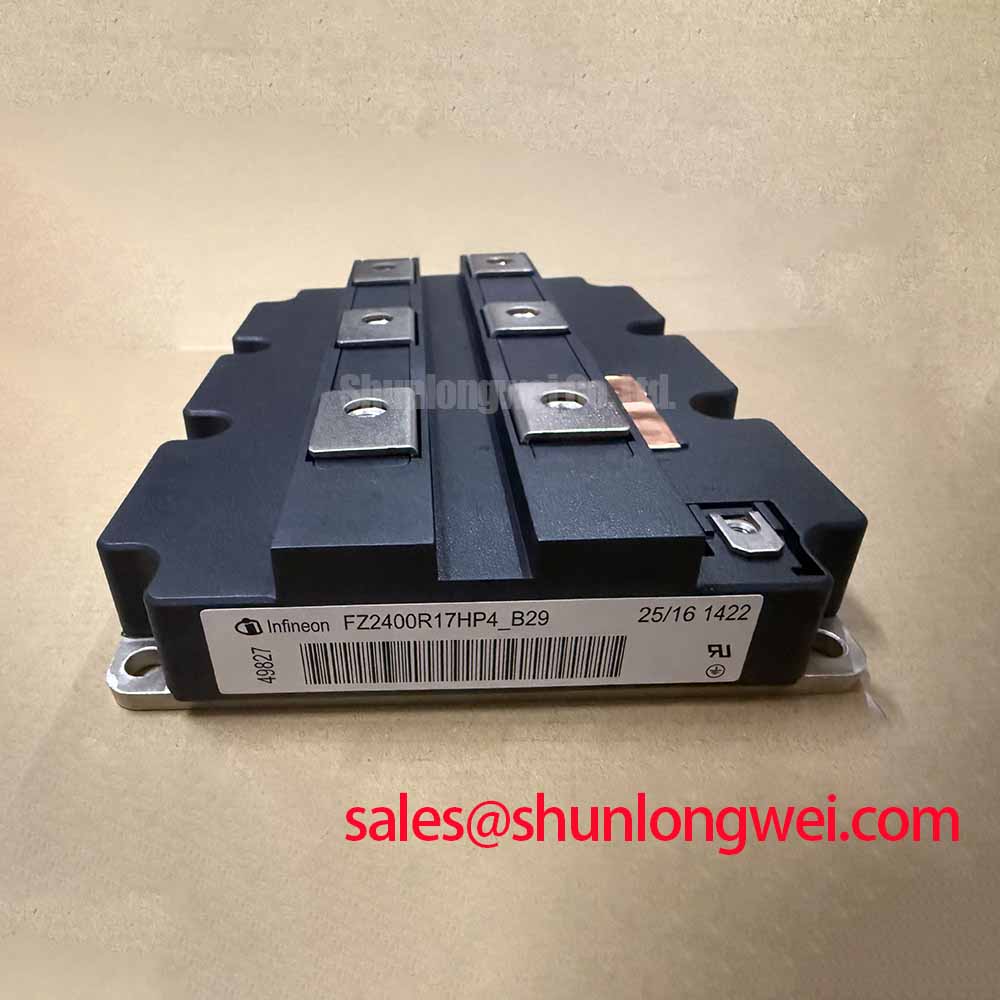

Technical Analysis for High-Power Systems
The standout feature of the FZ2400R17HP4_B29 is its nominal collector current (ICnom) of 2400 A. This substantial current-handling capability is made possible by Infineon’s TRENCHSTOP™ IGBT4 technology. This technology provides a low collector-emitter saturation voltage (VCEsat) of 2.15 V (typical at nominal current, Tvj=125°C). Lower VCEsat directly results in reduced conduction power loss (Pcond = VCEsat * IC), a dominant factor in high-current applications. This efficiency is critical for minimizing waste heat and improving the overall energy conversion efficiency of the end system. A robust gate drive design is essential to fully leverage these characteristics.
Effective thermal management is fundamental to reliability in high-power modules. The FZ2400R17HP4_B29 addresses this with a very low thermal resistance from junction to case (RthJC) of 0.008 K/W per IGBT. Thermal resistance can be compared to the width of a pipe; a lower value indicates a wider pipe, allowing heat to flow away from the semiconductor junction more easily. This excellent thermal transfer, combined with a high maximum operating junction temperature (Tvj op) of 150°C, provides a significant thermal margin. This allows the module to operate reliably under heavy loads and simplifies the design of the system’s cooling solution.


Optimized Application Scenarios
The specifications of this module are tailored for specific high-demand industrial applications:
- Wind Turbine Inverters: The 1700V blocking voltage and 2400A current rating are ideal for converting DC power from multi-megawatt wind turbines to grid-compliant AC.
- High-Power Industrial Drives: Its robust thermal performance and high power density make it suitable for controlling large industrial motors in applications like mining, marine propulsion, and heavy manufacturing.
- Grid Infrastructure: Well-suited for use in Flexible AC Transmission Systems (FACTS) and utility-scale power converters where reliability and efficiency are paramount.
- Medium-Voltage Converters: The module serves as a core building block for modular multi-level converters (MMCs) and other medium-voltage topologies.
This module is best suited for megawatt-scale converters where thermal stability and high current density are primary design constraints.
Key Technical Specifications
| Key Parameters for FZ2400R17HP4_B29 | |
|---|---|
| Absolute Maximum Ratings | |
| Collector-Emitter Voltage (VCES) | 1700 V |
| Continuous DC Collector Current (IC nom) | 2400 A (TC = 80°C) |
| Operating Temperature (Tvj op) | -40 to 150 °C |
| Electrical Characteristics (at Tvj = 25 °C unless otherwise specified) | |
| Collector-Emitter Saturation Voltage (VCEsat) at IC=2400A, VGE=15V | 2.15 V (Typ. at Tvj=125°C) |
| Gate-Emitter Threshold Voltage (VGE(th)) | 5.8 V (Typ.) |
| Gate-Emitter Leakage Current (IGES) | 400 nA (Max.) |
| Thermal and Mechanical Characteristics | |
| Thermal Resistance, Junction to Case (RthJC) per IGBT | 0.008 K/W |
| Mounting Torque, Terminals (M1) | 10 ± 1 Nm |
| Mounting Torque, Module (M2) | 10 ± 1 Nm |
Engineer’s FAQ
- 1. What are the main thermal management considerations for the FZ2400R17HP4_B29?
- Due to its high power dissipation, a low-resistance thermal interface material (TIM) and a high-performance heatsink are critical. The datasheet specifies a mounting force and torque for the housing and terminals to ensure minimal contact thermal resistance. Calculating total power losses (conduction and switching) is the first step to sizing the cooling system appropriately.
- 2. Can this module be used in parallel?
- Yes, the datasheet provides details for paralleling. Key considerations for successful paralleling include a symmetrical busbar layout to minimize stray inductance differences and ensuring balanced gate drive signals to promote even current sharing during switching events.
- 3. What does the TRENCHSTOP™ IGBT4 technology mean for my design?
- IGBT4 represents a balance between conduction and switching losses. Compared to previous generations, it offers lower VCEsat for reduced heat generation during the on-state, which is highly beneficial in applications with lower switching frequencies like industrial motor drives and wind converters.
- 4. What is the recommended gate-emitter voltage (VGE) for operation?
- The datasheet specifies static characteristics at a VGE of 15 V. The gate-emitter threshold voltage (VGE(th)) ranges from 5.2 V to 6.4 V. A robust gate drive circuit should provide a stable +15 V for turn-on and a negative voltage (e.g., -15 V) for turn-off to ensure noise immunity.
Enabling High-Power Density Designs
The FZ2400R17HP4_B29 provides the foundational switching performance for high-reliability, high-power density converters. Its combination of extremely high current capacity, robust thermal design, and proven IGBT4 technology empowers engineers to develop more compact and efficient power conversion systems for the most demanding industrial and renewable energy applications.