Mitsubishi CM100DU-12H Dual IGBT Module: A Technical Review
Mitsubishi CM100DU-12H | 600V 100A Dual IGBT Module
Introduction and Core Highlights
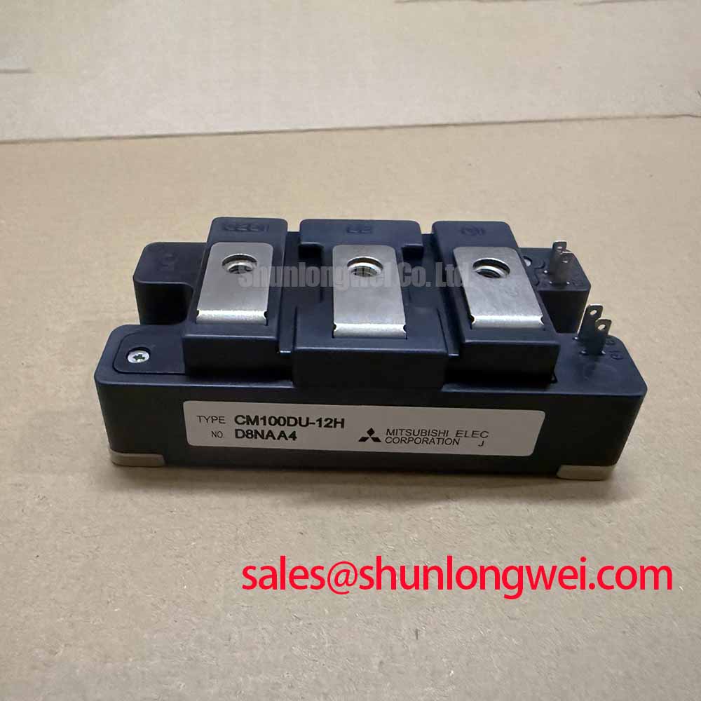
The Mitsubishi CM100DU-12H is a robust, electrically isolated 600V 100A dual IGBT module engineered for high-reliability industrial power conversion. This component integrates a half-bridge configuration into a single, insulated package, providing a streamlined solution that balances performance with straightforward implementation. It is particularly well-suited for building the foundational inverter legs in medium-power AC motor drives and uninterruptible power supplies.
- Core Specifications: 600V | 100A | 2500Vrms Isolation
- Key Advantages: Facilitates simplified inverter topologies and ensures high electrical isolation for system safety.
Download Official Datasheet (PDF)

Technical Analysis
Integrated Half-Bridge Configuration
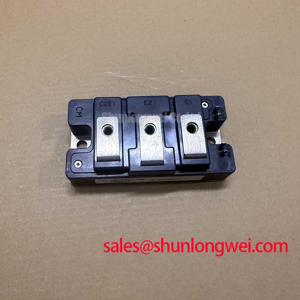
The CM100DU-12H features a dual IGBT, or half-bridge, topology within a single module. This design integrates two IGBTs and their corresponding super-fast recovery free-wheel diodes. For design engineers, this configuration simplifies the construction of inverter and chopper circuits. It reduces the component count, minimizes the complexity of busbar layouts, and helps lower stray inductance compared to using discrete components. This integration is a key factor in building more compact and reliable power stages for applications like power semiconductors based motor controls.
Robust Electrical Isolation
A critical feature for industrial hardware is electrical safety and noise immunity. The module specifies an isolation voltage (Visol) of 2500Vrms between the power terminals and the mounting baseplate. This high isolation level acts as a dependable safety barrier, preventing high voltages from reaching the system’s grounded chassis. It ensures operator safety and protects low-voltage control logic from potential damage during fault conditions. This characteristic is fundamental for creating durable and safe power systems in demanding industrial settings.
Quantifiable Thermal Performance
Effective thermal management is essential for the longevity of any power module. The datasheet specifies a maximum thermal resistance from junction to case (Rth(j-c)Q) of 0.31°C/W for the IGBT. This parameter can be imagined as the width of a pipe for heat flow; a lower value indicates that heat can escape the semiconductor junction more easily. This specific value is a crucial input for engineers when selecting an appropriate heatsink to ensure the device’s junction temperature remains safely below its 150°C maximum limit during operation.
Optimized Application Scenarios
The CM100DU-12H’s specifications make it a strong candidate for several common industrial applications:
- AC Motor Control: Its 600V/100A rating and half-bridge topology are ideal for constructing the inverter legs in variable frequency drives (VFDs) for industrial motors.
- Motion/Servo Control: The module’s fast-switching diodes and robust build handle the dynamic power requirements of precise servo drives.
- Uninterruptible Power Supplies (UPS): The integrated and isolated design enhances the reliability and safety of the DC-AC inverter stage in UPS systems.
- Welding Power Supplies: Capable of handling the high-current switching cycles required in modern welding equipment.
This module is best matched for power conversion systems where a reliable, isolated, and easy-to-implement half-bridge solution is required.
Key Specification Parameters
| Absolute Maximum Ratings (Tj = 25°C) | ||
|---|---|---|
| Collector-Emitter Voltage (VCES) | 600 V | |
| Collector Current (IC) | 100 A | |
| Maximum Collector Dissipation (Pc) | 400 W | |
| Junction Temperature (Tj) | -40 to 150 °C | |
| Electrical Characteristics (Tj = 25°C unless otherwise noted) | ||
| Collector-Emitter Saturation Voltage (VCE(sat)) @ 100A | 2.7 V (Max) | |
| Gate-Emitter Threshold Voltage (VGE(th)) | 5.5V / 8.5V (Typ/Max) | |
| Collector Cutoff Current (ICES) | 1 mA (Max) | |
| Thermal and Mechanical Characteristics | ||
| Thermal Resistance, Junction-to-Case (Rth(j-c)Q) | 0.31 °C/W (Max) | |
| Isolation Voltage (Visol, AC 1 min.) | 2500 Vrms | |
Engineer’s FAQ
What is the recommended mounting torque for the CM100DU-12H?
The datasheet specifies a mounting torque of 3.5 to 4.5 N·m for the M6 mounting screws. Adhering to this specification is critical to ensure a low thermal resistance path to the heatsink without inducing mechanical stress that could damage the module’s isolated baseplate.
How does the collector-emitter saturation voltage (VCE(sat)) impact thermal design?
The VCE(sat), with a maximum value of 2.7V at 100A, is a primary contributor to conduction losses. This loss generates heat (Power Loss ≈ VCE(sat) × IC). A clear understanding of this value is essential for calculating total power dissipation and designing an adequate cooling system to prevent IGBT failures from overheating.
What is the main benefit of the integrated free-wheeling diodes?
The module includes discrete super-fast recovery free-wheel diodes connected anti-parallel to the IGBTs. These diodes provide a path for inductive load current when the IGBTs are turned off, which is essential in motor drive and inverter circuits. Their fast recovery characteristic (trr) minimizes switching losses and improves overall system efficiency.
Closing Statement
The CM100DU-12H offers a dependable and practical foundation for industrial power conversion. Its integrated half-bridge circuit and robust electrical isolation empower engineers to develop compact, safe, and efficient motor drives and power supply systems with a validated and straightforward component.