Here are the requested meta title and meta description for the provided article. **Meta Title:** MCC26-14io1B Thyristor Module | Technical Review, Specs & Datasheet **Meta Description:** Explore a detailed technical review of the MCC26-14io1B dual thyristor module. Learn about its key specs (1400V, 26A, 3600V isolation), the advantages of its isolated TO-240AA package for simplified thermal design, and its use in industrial AC power controllers, soft starters, and rectifiers. Includes full datasheet specifications and an engineer’s FAQ.
## MCC26-14io1B Thyristor Module for Industrial AC Control
Technical Review of the MCC26-14io1B Thyristor Module
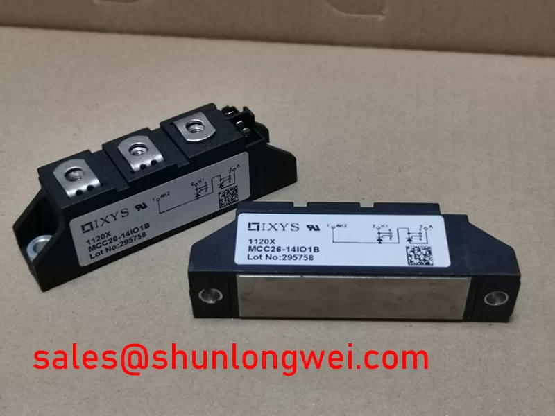
The MCC26-14io1B is a dual thyristor module engineered for reliable control of line-frequency AC power. Its primary value stems from a combination of high voltage capability and a thermally efficient, isolated package design. This integration provides engineers a robust component that simplifies mechanical and thermal assembly in demanding industrial systems.
* **Core Specifications**: 1400V | 26A (TC = 95°C) | 3600V~ Isolation
* **Key Engineering Advantages**:
* Simplified heatsink mounting due to a standard TO-240AA package with an electrically isolated base.
* Enhanced long-term stability and voltage blocking from planar glass passivated chips.
* The module’s Direct Copper Bonded (DCB) ceramic baseplate provides high electrical isolation, streamlining thermal design by potentially removing the need for external insulating layers.
Download the Official MCC26-14io1B Datasheet (PDF)

Technical Analysis for System Integration
The engineering value of the MCC26-14io1B is centered on its robust construction and electrical characteristics tailored for industrial environments. The module’s design directly addresses common challenges in power system assembly and long-term reliability.
The most significant feature is the TO-240AA package incorporating a Direct Copper Bonded (DCB) alumina (Al2O3) ceramic baseplate. This construction provides an RMS isolation voltage (VISOL) of 3600V~. For design engineers, this high level of isolation simplifies the mounting process onto a chassis or heatsink, as it often eliminates the need for additional, thermally resistive insulating pads. The module’s junction-to-case thermal resistance (RthJC) is specified at 1.0 K/W for each internal thyristor. To use an analogy, this thermal resistance is like the width of a pipe for heat; the low value signifies a wide, efficient path for thermal energy to move from the active silicon to the heatsink, which is critical for maintaining junction temperatures within safe operating limits.
Reliability under high-voltage conditions is supported by the use of planar passivated chips. Glass passivation is a process that protects the sensitive high-voltage junction of the thyristor from contaminants and electrical field stress. This results in stable blocking voltage (VDRM/VRRM) of 1400V over the component’s operational life, a critical factor for equipment connected directly to industrial AC mains.
Optimized Application Scenarios
The specific characteristics of the MCC26-14io1B make it a suitable component for several power control applications:
* **AC Power Controllers**: Ideal for industrial heating and lighting control systems where its high blocking voltage provides a significant safety margin on 400V and 480V AC lines.
* **Motor Soft Starters**: The module’s ability to handle high non-repetitive surge currents (ITSM up to 520A) allows it to safely manage the initial inrush current of AC motors.
* **Controlled Rectifiers**: Two modules can be configured to create a single-phase fully-controlled bridge rectifier, offering precise control over the DC output voltage for battery charging or DC motor drives.
* **Solid State Relays**: Provides a robust foundation for building high-power AC solid-state relays for switching industrial loads.
Its 1400V rating and isolated package make it a best-fit for line-voltage AC control systems requiring simplified thermal design and high reliability.
Key Technical Specifications
This table contains performance parameters for the MCC26-14io1B, derived directly from the official manufacturer datasheet.
| Absolute Maximum Ratings (Tvj = 25°C unless otherwise specified) | |
|---|---|
| Repetitive Peak Reverse/Off-State Voltage (VRRM/VDRM) | 1400 V |
| Average On-State Current (ITAV, TC=95°C) | 26 A |
| RMS On-State Current (ITRMS) | 45 A |
| Peak Surge Current (ITSM, t=10ms, 50Hz, sine) | 520 A |
| Operating Junction Temperature Range (Tvj) | -40 to +125 °C |
| Electrical & Gating Characteristics (Tvj = 25°C) | |
| Gate Trigger Current (IGT) | max. 100 mA |
| Gate Trigger Voltage (VGT) | max. 1.5 V |
| On-State Voltage (VT, IT=80A) | max. 1.7 V |
| Thermal and Mechanical Specifications | |
| Thermal Resistance, Junction to Case (RthJC) | 1.0 K/W (per Thyristor) |
| Isolation Voltage (VISOL, 50/60 Hz, RMS, t=1min) | 3600 V~ |
| Mounting Torque (Terminals / Mounting) | 1.8-2.2 Nm / 4.8-6.0 Nm |
| Typical Module Weight | 30 g |
Engineer’s FAQ
What is the primary factor for calculating the required heatsink for the MCC26-14io1B?
The key parameter is the thermal resistance from junction to case (RthJC), which is 1.0 K/W per thyristor. To calculate the required heatsink thermal resistance (RthCH), you must first determine the power dissipation of each thyristor in your application. The total thermal resistance from the junction to ambient air must be low enough to keep the junction temperature (Tvj) below its maximum rating of 125°C under worst-case operating conditions.
What is the correct mounting procedure for this module?
To ensure proper thermal transfer, the heatsink surface should be flat and clean. Apply a thin, uniform layer of thermal grease before mounting. Secure the module to the heatsink using two M5 screws, tightening them to the recommended torque of 4.8 to 6.0 Nm. The electrical terminals should be tightened to 1.8 to 2.2 Nm. Uneven or excessive torque can damage the ceramic substrate and compromise thermal performance.
What does the common cathode configuration simplify?
The common cathode configuration, where the cathodes of the two internal thyristors are connected to a single terminal, is advantageous for building AC controllers (phase control) or certain rectifier topologies. It simplifies the power wiring layout, as only one connection is needed for the common return path of the two controlled legs.
Are these thyristors suitable for high-frequency applications?
No, this module is specified as a “thyristor for line frequency”. Its switching characteristics are optimized for applications operating at 50/60 Hz. Use in high-frequency circuits would result in excessive switching losses and potential device failure.
Enabling Robust Power Control
The MCC26-14io1B delivers a well-defined set of electrical and thermal characteristics in an industry-standard package. Its high isolation voltage and proven passivated silicon technology provide the foundation for reliable and straightforward implementation in a range of industrial AC power control and conversion systems, from servo drives to welding power supplies. The design facilitates efficient thermal management, enabling engineers to develop compact and dependable end-products. For more information on related technologies, explore the role of intelligent power modules (IPM) in modern systems.