Based on the technical review provided, you mention that the module’s low thermal resistance (Rth(j-c)) of 0.4 K/W per diode helps in designing more compact cooling systems or operating at higher power levels. Could you elaborate on this? Specifically, using the data from the document, what would be the maximum power dissipation allowed per diode if the system must operate at a maximum case temperature (Tc) of 75°C while ensuring the junction temperature (Tvj) does not exceed its 125°C limit? Please show the calculation.
## SKKD 81/12 Diode Module: Technical Review for Power Rectifiers
The SKKD 81/12 is a Rectifier Diode Module from Semikron, engineered for robust performance in industrial power conversion systems. Its core value proposition lies in delivering high reliability and efficient rectification through a design that incorporates hard-soldered joints and effective thermal management. This module is configured with two series-connected diodes within a single SEMIPACK® 1 housing.
* **Core Specifications**: 1200V | 82A | 1750A IFSM
* **Key Advantages**: High electrical and thermal cycling capability, simplified thermal design due to low thermal resistance.
* **Engineering Focus**: The module’s construction with an isolated metal baseplate ensures efficient heat dissipation, a critical factor for maintaining system reliability under continuous load.
Access SKKD 81/12 Documentation
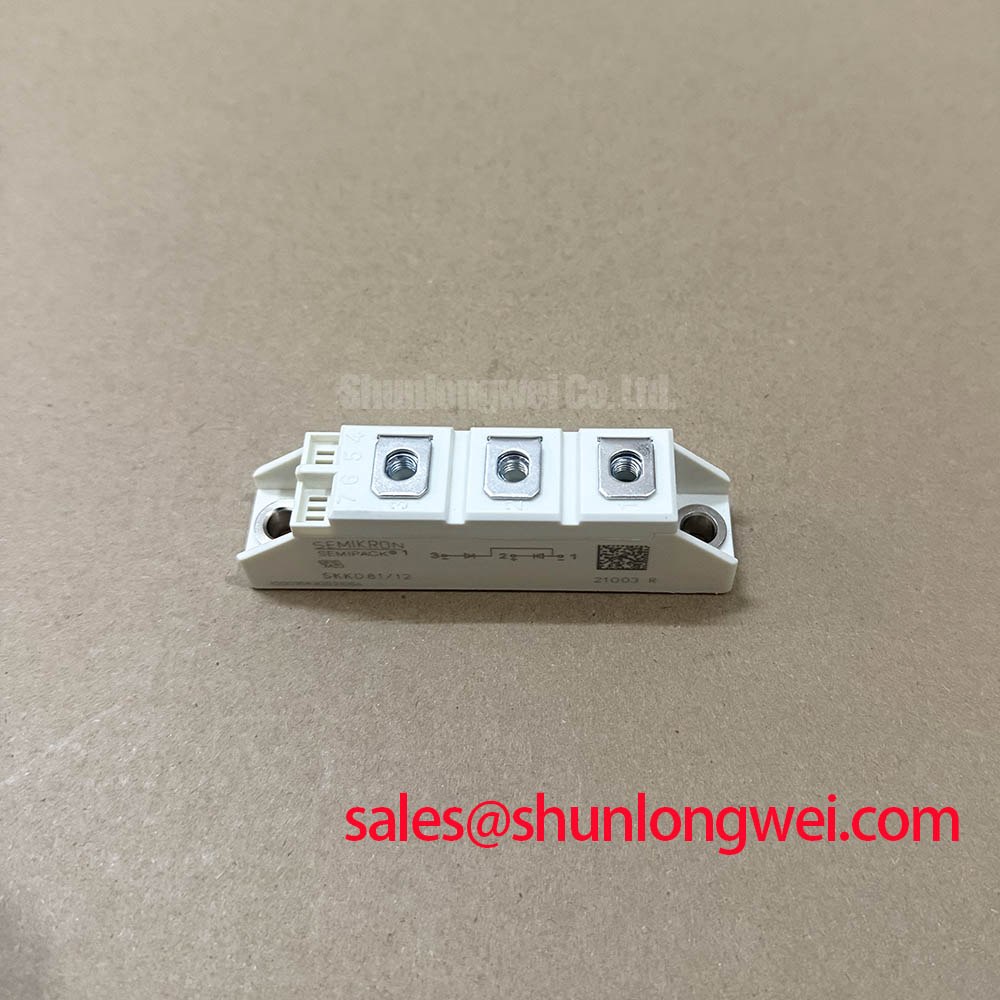


Technical Analysis for System Integration
The SKKD 81/12 module’s design directly addresses long-term operational stability. Its use of hard-soldered joints provides a mechanically strong and reliable electrical connection, which is critical in environments with thermal cycling and vibration. This construction method minimizes the risk of joint fatigue over the component’s lifetime.
Effective thermal management is streamlined by the module’s low junction-to-case thermal resistance (Rth(j-c)) of 0.4 K/W per diode. This parameter can be thought of like the width of a pipe; a lower value indicates a wider pipe, allowing heat to flow more easily from the active semiconductor junction to the heatsink. This efficiency allows engineers to design more compact cooling systems or operate at higher power levels without exceeding the maximum junction temperature of 125 °C. The module’s aluminum oxide ceramic isolated baseplate is key to achieving this thermal performance.
Optimized Application Scenarios
The electrical and thermal characteristics of the SKKD 81/12 make it highly suitable for a range of power rectification applications.
* **Line Rectifiers for Motor Drives:** Its high surge current rating (IFSM) of 1750A at a 125 °C junction temperature allows it to safely manage the inrush currents that occur during motor startup.
* **Non-controllable Rectifiers for AC/AC Converters:** The 1200V repetitive peak reverse voltage (VRRM) provides a sufficient safety margin for direct rectification from industrial AC lines.
* **Field Supply for DC Motors:** The module provides a straightforward and robust solution for generating the DC voltage required for motor field windings.
* **Industrial Power Supplies:** Its UL-recognized status (File No. E 63 532) and isolated baseplate simplify system safety compliance and assembly.
This module is best suited for industrial power systems where high reliability and efficient thermal performance are primary design requirements.
Key Specifications of the SKKD 81/12
| Parameter | Value | Conditions |
|---|---|---|
| Absolute Maximum Ratings | ||
| Repetitive Peak Reverse Voltage (VRRM) | 1200 V | – |
| Average Forward Current (IFAV) | 82 A | sin. 180°; Tc = 85 °C |
| Peak Forward Surge Current (IFSM) | 1750 A | Tvj = 125 °C; 10 ms |
| I²t Value | 15000 A²s | Tvj = 125 °C; 8.3 … 10 ms |
| Electrical Characteristics | ||
| Forward Voltage (VF) | ≤ 1.55 V | Tvj = 25 °C; IF = 300 A |
| Threshold Voltage (V(TO)) | 0.85 V | Tvj = 125 °C |
| Slope Resistance (rT) | 1.8 mΩ | Tvj = 125 °C |
| Thermal and Mechanical Characteristics | ||
| Thermal Resistance, Junction to Case (Rth(j-c)) | 0.4 K/W | Per diode |
| Operating Junction Temperature (Tvj) | -40 to +125 °C | – |
| Mounting Torque | 5 ± 15 % Nm | To heatsink (M6) |
Engineer’s FAQ
What is the maximum surge current the SKKD 81/12 can handle?
The module can handle a non-repetitive peak forward surge current (IFSM) of 2000 A for a 10 ms pulse at a starting junction temperature of 25°C. This tolerance drops to 1750 A if the starting junction temperature is 125°C.
What are the recommended mounting torque specifications?
For a reliable thermal and mechanical connection, the recommended mounting torque for the M6 bolts to the heatsink is 5 Nm ± 15%. The M5 electrical terminals should be tightened to 3 Nm ± 15%. Adhering to these values is crucial for proper heat transfer and preventing damage.
How does the isolated baseplate benefit the design?
The aluminum oxide ceramic isolated baseplate simplifies assembly by allowing the module to be mounted directly to a grounded heatsink without requiring additional insulating materials. This reduces component count, assembly time, and potential points of failure. The design provides an isolation voltage (Visol) of 3000V~ for 1 minute.
How is the SKKD 81/12 configured internally?
The module contains two rectifier diodes connected in series, with a center tap. The terminals are marked 1 (common anode-cathode), 2 (cathode), and 3 (anode), providing a flexible building block for various rectifier circuits.
The integration of hard-soldered joints and an efficient thermal path via its ceramic-isolated baseplate makes the SKKD 81/12 a durable component for demanding industrial applications. Its electrical characteristics are well-suited for designers building reliable and long-lasting power rectification stages in motor drives and power supplies. For further details on thermal design and application, consider resources on mastering thermal design or understanding isolated baseplates.