Mitsubishi PM50CL1B120: A Technical Review of an All-in-One CIB IPM
PM50CL1B120 Mitsubishi 1200V 50A CIB IPM Technical Review
Introduction and Core Highlights
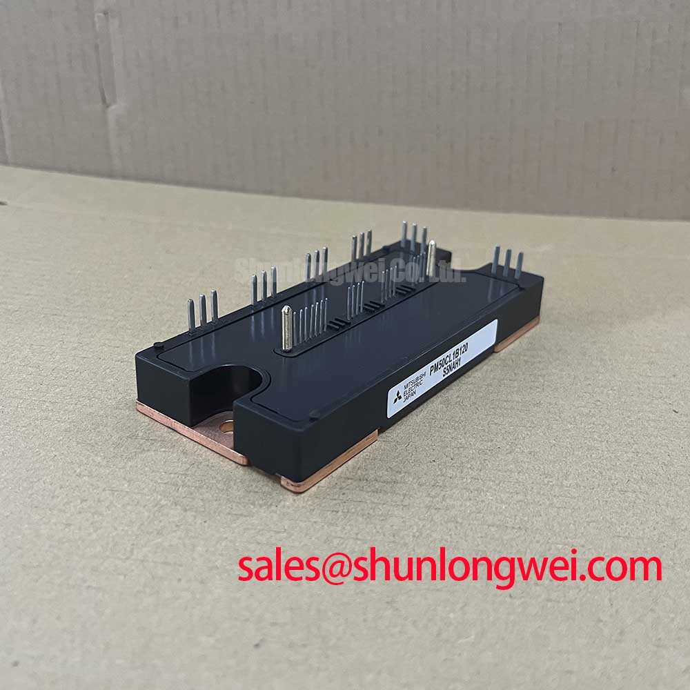
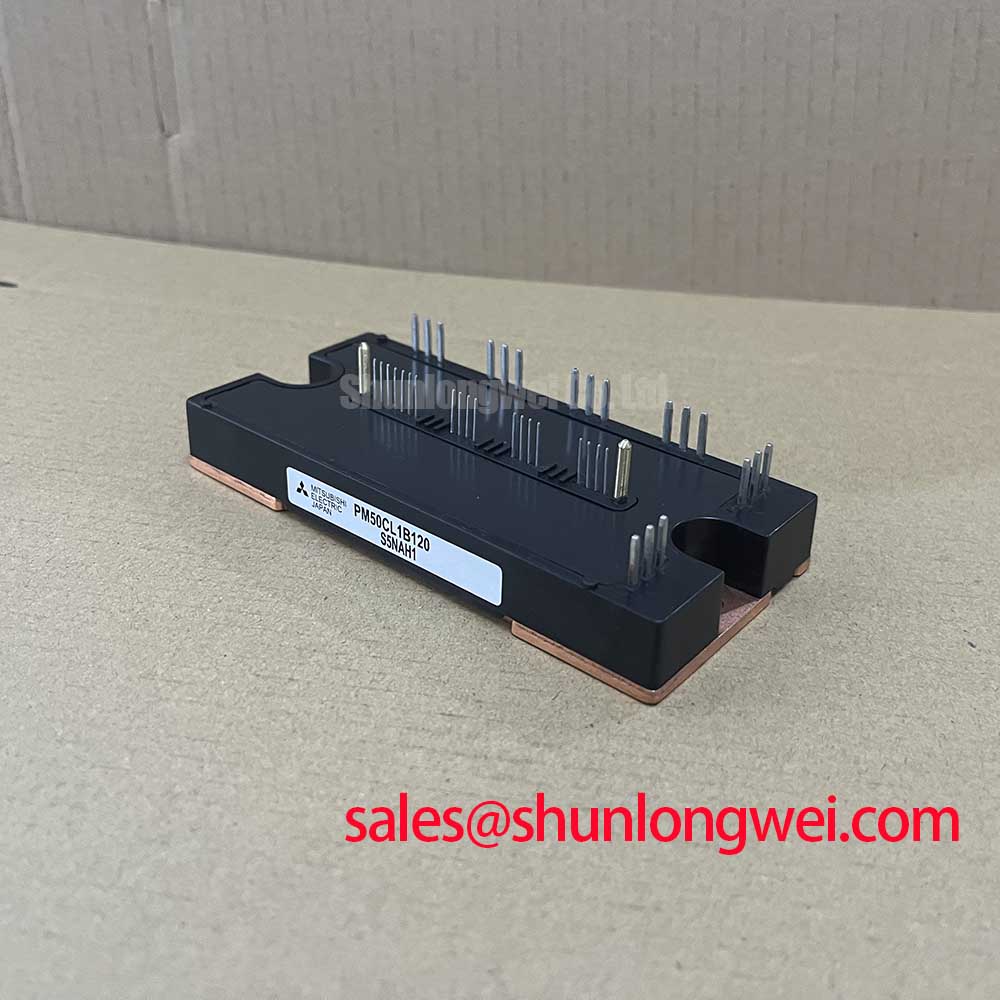
The Mitsubishi PM50CL1B120 is a highly integrated CIB (Converter-Inverter-Brake) Intelligent Power Module (IPM) that streamlines the development of compact and reliable motor control systems. By combining a three-phase diode converter, a three-phase IGBT inverter, and a brake chopper into a single package, this module significantly reduces component count and design complexity. It incorporates Mitsubishi’s 5th generation CSTBT™ (Carrier Stored Trench-Gate Bipolar Transistor) technology to balance conduction and switching losses effectively. The integration of drive circuitry and comprehensive protection functions makes it a robust solution for variable frequency drives.
- Core Specifications: 1200V | 50A | Integrated CIB Topology
- Key Advantages: Simplifies PCB layout, enhances system reliability with built-in protections.
For engineers wondering how to accelerate the design of a motor drive’s power stage, the PM50CL1B120 offers a compelling answer by consolidating key power and protection stages into one validated component.
Download Official Datasheet (PDF)
Technical Deep Dive: Integration and Protection
The primary engineering advantage of the PM50CL1B120 is its all-in-one CIB configuration. This architecture integrates the AC-to-DC rectification (converter), DC-to-AC inversion (inverter), and regenerative energy management (brake chopper) stages. This consolidation is central to The IPM Advantage, as it minimizes the parasitic inductance between power stages that is common in discrete designs. Lower inductance reduces voltage overshoots during high-speed switching, which in turn diminishes EMI and improves overall system stability.


Embedded Protection for System Robustness
Reliability is fortified through a suite of on-board protection circuits. The PM50CL1B120 provides detection and protection against short-circuits (SC), over-temperature (OT), and control supply under-voltage (UV). The over-temperature protection is particularly crucial; it uses a sensor that directly monitors the IGBT chip’s surface temperature. This function acts like a vigilant sentinel, sending a fault signal to the microcontroller before excessive heat can cause irreversible damage. This is analogous to a car’s engine management system cutting power when it detects critical overheating, thus preventing catastrophic failure. This integrated approach to protection is a core tenet of modern power semiconductors.

Optimized Application Scenarios
The PM50CL1B120 is engineered for systems where space, reliability, and time-to-market are key design constraints.
- General-Purpose Inverters: The module’s 1200V rating provides a robust safety margin for 400-480V AC line applications, while the CIB topology offers a complete power stage solution.
- AC Servo Drives: High integration and built-in protection are critical for the dynamic and precise control loops in servo systems, making this IPM an ideal fit.
- Industrial Motor Control: For pumps, fans, and conveyors, this module simplifies the power electronics, reducing both assembly time and potential points of failure.
- Small Material Handling Vehicles: Its compact footprint and regenerative braking capability are well-suited for the drive systems in small forklifts or automated guided vehicles (AGVs).
Its integrated feature set makes it a best-match for motor drives up to approximately 22 kW, providing a complete, verified power stage solution.
Key Specification Parameters
| Absolute Maximum Ratings (Tj=25°C) | |
|---|---|
| Collector-Emitter Voltage (VCES) | 1200V |
| Inverter Collector Current (±IC) | 50A |
| Inverter Collector Current Peak (±ICP) | 100A |
| Brake Collector Current (IC) | 50A |
| Isolation Voltage (Viso) | 2500V (AC, 1 minute) |
| Operating Junction Temperature (Tj) | -20°C to 150°C |
| Electrical Characteristics (Tj=125°C) | |
| Inverter Collector-Emitter Saturation Voltage (VCE(sat)) | 2.2V (typ) at IC=50A |
| Brake Collector-Emitter Saturation Voltage (VCE(sat)) | 2.5V (typ) at IC=50A |
| Converter Forward Voltage (VF) | 1.8V (typ) at IF=50A |
| Thermal Characteristics | |
| Thermal Resistance, Junction-to-Case (Rth(j-c)) – Inverter IGBT | 0.27 °C/W (per module) |
Engineer’s FAQ
- How does the PM50CL1B120 simplify motor drive design?
- It integrates a three-phase converter, inverter, brake chopper, gate drivers, and protection circuits into a single module. This eliminates the need to select, source, and validate numerous discrete components, drastically reducing PCB complexity and assembly time as outlined in guides on PIM vs. discrete IGBT design.
- What are the key considerations for heatsink mounting?
- Proper thermal management is essential. The module’s baseplate must make flat, uniform contact with the heatsink. A thermal grease with high conductivity should be applied evenly, and mounting screws must be tightened to the specified torque (3.5 – 4.5 N·m) to ensure low thermal resistance and prevent mechanical stress on the isolated substrate.
- How does the module signal a short-circuit or over-temperature fault?
- The PM50CL1B120 provides a dedicated fault output pin (Fo). In the event of a short-circuit, over-temperature, or supply under-voltage condition, this open-collector pin is activated, pulling low to signal the fault to the system’s master controller.
- Can the brake chopper handle high-energy regenerative braking?
- The brake chopper is rated for the same collector current (50A) as the inverter section. However, its capacity to dissipate energy is dependent on the duty cycle and the external braking resistor. Designers must calculate the braking energy and ensure the resistor and the module’s thermal dissipation capability are sufficient for the application’s regenerative needs.
Enabling Compact and Reliable Power Conversion
The PM50CL1B120 provides a robust, verified foundation for motor control systems. Its high level of integration of power and protection functions empowers engineers to bypass significant design and validation overhead. This allows for the creation of more compact, reliable, and cost-effective inverter and servo drive solutions, accelerating the path from concept to production.