Fuji Electric 6MBI30L-060: A Robust IGBT Module for Industrial Power Conversion
## Fuji Electric 6MBI30L-060 IGBT Module: 600V / 30A
A Robust 6-Pack Module for Industrial Power Conversion
The Fuji Electric 6MBI30L-060 is a 6-pack IGBT module providing an integrated solution for three-phase inverter systems. This L-Series module combines six Non-Punch-Through (NPT) IGBTs and six freewheeling diodes into a single, compact package, streamlining the design of motor drives and other power conversion applications. It focuses on delivering reliable performance and simplifying the system layout.
* **Core Specifications:** 600V | 30A | VCE(sat) 2.7V (max)
* **Key Advantages:**
* Reduces component count and simplifies PCB design.
* NPT technology provides inherent ruggedness and a wide Safe Operating Area (SOA).
For detailed electrical and thermal specifications, refer to the official documentation: Download Official Datasheet (PDF)
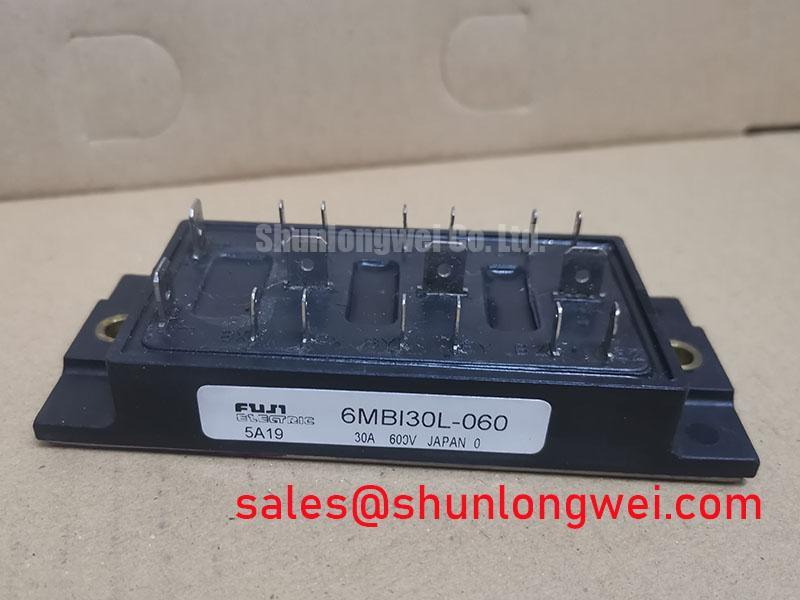

Technical Analysis for System Design
The 6MBI30L-060 module’s primary value lies in its high level of integration. By housing a full three-phase bridge, it allows engineers to reduce manufacturing complexity and minimize the parasitic inductance often found in systems built with discrete components. This consolidated design is a key factor in achieving stable and reliable switching performance in motor drive applications.
Central to its performance is the use of NPT (Non-Punch-Through) IGBT technology. While later technologies focus on switching speed, NPT provides exceptional ruggedness. This structure is inherently more resistant to transient voltage spikes and offers a robust short-circuit withstand capability, which is a significant advantage in demanding industrial environments.
Efficient thermal management is critical for power module longevity. The thermal resistance of a module can be thought of as the width of a pathway for heat to escape. The 6MBI30L-060 specifies a thermal resistance (junction-to-case) of 0.83°C/W per IGBT. This value indicates an efficient path for dissipating heat from the silicon die to the heatsink, helping to keep the junction temperature within safe operating limits during continuous operation.


Optimized Application Scenarios
The electrical and thermal characteristics of the 6MBI30L-060 are well-suited for specific power conversion systems.
* **General-Purpose Inverters:** Its 600V/30A rating and integrated 6-in-1 configuration make it a practical choice for small to medium-sized variable frequency drives (VFDs).
* **AC Servo Drives:** The module provides the complete three-phase inverter stage needed for precise position and speed control in industrial automation.
* **Uninterruptible Power Supplies (UPS):** A compact and reliable building block for the inverter stage in small commercial UPS systems.
* **Industrial Robotics:** Suitable for powering the multi-axis robotic arms that require coordinated motor control.
Its integrated nature and robust NPT silicon make it a strong candidate for cost-effective motor control systems requiring proven reliability over high-frequency performance.
Key Specifications of the 6MBI30L-060
| Parameter | Symbol | Value | Unit |
|---|---|---|---|
| Absolute Maximum Ratings (Per IGBT) | |||
| Collector-Emitter Voltage | VCES | 600 | V |
| Gate-Emitter Voltage | VGES | ±20 | V |
| Continuous Collector Current (Tc=80°C) | IC | 30 | A |
| Collector Power Dissipation (1 Device) | PC | 120 | W |
| Electrical Characteristics (Per IGBT) | |||
| Collector-Emitter Saturation Voltage | VCE(sat) | 2.2 (Typ) / 2.7 (Max) | V |
| Gate-Emitter Threshold Voltage | VGE(th) | 5.0 to 8.0 | V |
| Thermal Characteristics | |||
| Thermal Resistance (Junction to Case, per IGBT) | Rth(j-c) | 0.83 | °C/W |
| Operating Junction Temperature | Tj | +150 | °C |
Engineer’s FAQ
1. What is the recommended mounting torque for the 6MBI30L-060?
The datasheet specifies a mounting screw torque of 1.5 ± 0.2 Nm. Applying incorrect torque can lead to poor thermal contact with the heatsink or physical stress on the module’s substrate. Insufficient torque increases thermal resistance, while excessive torque can cause cracks or warping, both of which degrade reliability and lifespan. Proper torque is essential for effective thermal management.
2. How do I calculate the required heatsink performance?
To determine the required heatsink-to-ambient thermal resistance (Rth(c-a)), you first calculate the total power dissipation (P_total) from conduction and switching losses under your operating conditions. Then use the formula: Rth(c-a) = (Tj_max – Ta) / P_total – Rth(j-c) – Rth(c-s). Where Tj_max is the maximum junction temperature (150°C), Ta is the ambient temperature, Rth(j-c) is from the datasheet (0.83°C/W for the IGBT), and Rth(c-s) is the thermal resistance of the thermal interface material.
3. Is a negative gate voltage required to ensure the IGBTs are off?
While a 0V gate-emitter voltage (Vge) will turn the device off, applying a small negative voltage (e.g., -5V to -15V) is a common practice in robust gate drive design. This provides a larger noise margin, preventing unintended turn-on caused by dV/dt transients or parasitic gate coupling, which is crucial in noisy inverter environments.
4. What is the role of the freewheeling diodes (FWD) in this module?
The FWDs provide a path for the inductive load current to flow when an IGBT is turned off in a three-phase motor drive. Without them, the high voltage spike from the motor’s inductance would destroy the IGBTs. The performance of the FWD, particularly its recovery time (trr), is critical for system efficiency and EMI.
The 6MBI30L-060 offers a proven, integrated foundation for power electronics engineers tasked with developing cost-effective and reliable low-to-medium power motor control systems.