Mitsubishi Electric CM20MD-12H: 600V 20A CIB IGBT Module for Industrial Motor Control
CM20MD-12H Mitsubishi Electric IGBT Module | 600V 20A CIB
Efficient Power Integration for Industrial Motor Control
The Mitsubishi Electric CM20MD-12H is a specialized CIB (Converter Inverter Brake) module engineered to streamline the design of compact AC motor drives and power semiconductors systems. By integrating a three-phase diode bridge converter, a six-pack IGBT inverter, and a dedicated brake circuit into a single MD-style package, this component significantly reduces the physical footprint and complexity of the power stage. It is particularly effective for engineers looking to balance power density with robust electrical isolation.
- Core Specifications: 600V | 20A | VCE(sat) 2.4V (Typical at 25°C)
- Key Advantages: Minimized parasitic inductance through internal busbar optimization; simplified thermal management via an isolated baseplate.
- Technical Intent: This module addresses the common engineering challenge of reducing assembly time while maintaining high reliability in 220V/240V class industrial drives.
Download Official Datasheet (PDF)
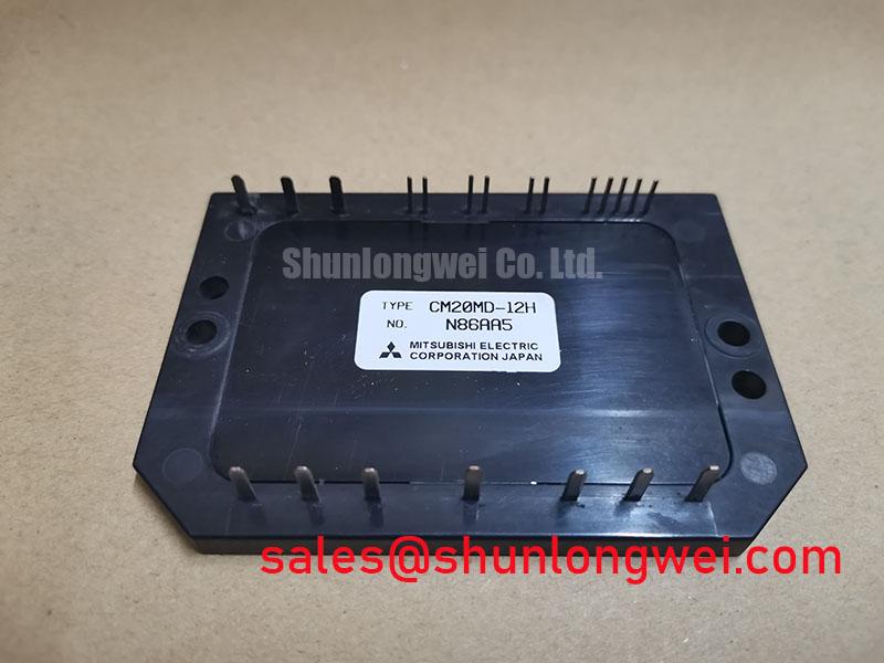
Technical Analysis: Efficiency Through CIB Integration
The CM20MD-12H is defined by its Converter-Inverter-Brake (CIB) topology. In traditional designs, engineers must source separate discrete components for the rectification and inversion stages, which increases the cumulative parasitic inductance of the external wiring. The CM20MD-12H mitigates this by housing the entire 3-phase AC-to-DC-to-AC conversion path within one module. This internal integration is crucial for minimizing voltage spikes during high-frequency switching, as discussed in our guide on PIM vs. Discrete IGBT strategic choices.
One of the most critical electrical parameters for this module is the Collector-Emitter Saturation Voltage ($V_{CE(sat)}$). Rated at a typical 2.4V, this value represents the efficiency of the device when fully “on.” You can think of $V_{CE(sat)}$ as the “friction” in a water valve; a lower value means energy flows through the device with minimal resistance, reducing the amount of power wasted as heat. For the CM20MD-12H, this low conduction loss directly translates to a smaller requirement for cooling fans and heatsinks, enabling more compact enclosure designs.

Furthermore, the Isolated Baseplate technology utilizes a ceramic insulation layer that provides 2500Vrms of isolation between the internal circuitry and the mounting surface. This feature allows multiple modules to be mounted to a single grounded heatsink without the need for additional external insulation pads, which often act as thermal bottlenecks. Efficient heat transfer is vital for maintaining the longevity of the silicon chips, especially during high-torque startup phases in motor applications.
Optimized Application Scenarios
The CM20MD-12H is specifically designed for low-to-medium power industrial environments where reliability and space are paramount:
- Variable Frequency Drives (VFDs): The integrated converter stage makes this module an all-in-one solution for small AC drives (up to 2.2kW depending on cooling).
- Servo Motor Controllers: Precise switching characteristics and low drive power requirements allow for the high-dynamic performance needed in robotics and CNC machinery.
- Industrial Pumps and Fans: The 600V rating is ideally suited for standard 200V-240V AC line inputs commonly found in HVAC and fluid management systems.
- Uninterruptible Power Supplies (UPS): Efficient inversion and a dedicated brake circuit provide the necessary building blocks for power backup stages.
Conclusion: This module is the best match for designers prioritizing assembly speed and high power density in 240V industrial AC motor control applications.

Key Specifications Table
| Parameter Group | Specific Rating | Value (Max/Typ) |
|---|---|---|
| Absolute Maximums | Collector-Emitter Voltage ($V_{CES}$) | 600V |
| Current Ratings | Collector Current ($I_C$) | 20A |
| Pulsed Current | Peak Collector Current ($I_{CP}$) | 40A |
| Electrical Characteristics | Saturation Voltage ($V_{CE(sat)}$) | 2.4V (Typ) |
| Isolation | Isolation Voltage ($V_{isol}$) | 2500 Vrms |
| Package | Type | MD Package (CIB) |

Engineer FAQ
Q1: What are the recommended mounting torque settings for the CM20MD-12H?
A: To ensure optimal thermal contact and prevent mechanical stress, the mounting screws should be tightened to a range of 2.5 to 3.5 N.m. Over-tightening can crack the ceramic insulation, while under-tightening leads to thermal runaway.
Q2: Is the CM20MD-12H suitable for a high-frequency switching application above 20kHz?
A: While the IGBTs are capable of fast switching, thermal losses increase linearly with frequency. For applications above 15-20kHz, careful de-rating is required to ensure the junction temperature stays within safe operating limits.
Q3: How does the integrated brake circuit work in this module?
A: The brake circuit consists of a single IGBT and a freewheeling diode. It is used to dissipate regenerative energy from the motor into an external resistor during deceleration, preventing the DC bus voltage from exceeding safe levels.
Q4: How do I manage heat cycles to avoid wire bond fatigue?
A: Thermal design should focus on minimizing the $Delta T_j$ (junction temperature swing). Implementing a robust heatsink and ensuring high-quality thermal interface material (TIM) are essential. For more details, refer to our analysis on IGBT reliability and cycling curves.
Professional Summary
The CM20MD-12H represents a balanced engineering solution for industrial motor control, combining converter, inverter, and brake functions into a single thermally optimized MD package. By leveraging its low $V_{CE(sat)}$ and high isolation voltage, engineers can achieve higher power density and reduced assembly costs without sacrificing the electrical robustness required for harsh industrial environments. This Mitsubishi Electric module remains a dependable choice for 240V AC drive architectures focusing on efficiency and spatial economy.