Technical Guide to the Semikron SKM400GAR124D 1200V 400A IGBT Chopper Module
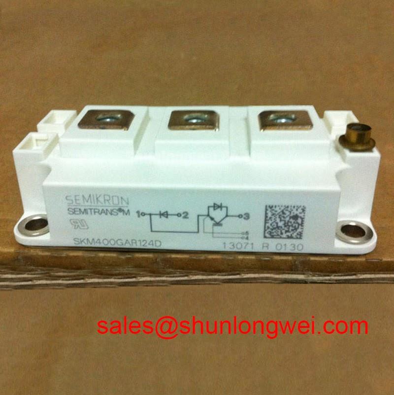
SKM400GAR124D Semikron 1200V 400A IGBT Chopper Module
Introduction and Core Highlights
The SKM400GAR124D is a high-power SEMITRANS 3 IGBT module engineered by Semikron for efficient series chopper and boost converter applications. Rated at 1200V and 400A, this module integrates low-loss trench gate IGBT technology with a Controlled Axial Lifetime (CAL) freewheeling diode to minimize dynamic power dissipation. Engineers looking to optimize thermal designs in harsh industrial environments can rely on its isolated copper baseplate, which guarantees exceptional heat transfer and electrical isolation.
- Core Ratings: 1200V | 400A | VCE(sat) 1.70V (typical)
- Engineering Value: Significant reduction in transient thermal impedance and simplified gate drive requirements.
- Application Intent: This module resolves common thermal dissipation bottlenecks in heavy-duty step-up converters.
Download Official SKM400GAR124D Datasheet (PDF)


Technical Analysis Around Switching Efficiency and Thermal Path
Conduction loss mitigation in the SKM400GAR124D relies on its optimized trench gate evolution. By reducing the collector-emitter saturation voltage (VCE(sat)) to a typical value of 1.70V at nominal current, static losses during the conduction phase are minimized. This electrical efficiency is paired with a highly rugged Reverse Bias Safe Operating Area (RBSOA), allowing the device to safely turn off inductive loads up to twice its rated current without voltage-induced breakdown.
To understand the module’s reliability, consider its thermal design. You can think of thermal resistance as a narrow water pipe; a lower resistance allows thermal energy to flow more easily from the semiconductor junction to the heatsink, keeping internal temperatures well within safe limits. With a junction-to-case thermal resistance (Rth(j-c)) of just 0.05 K/W for the IGBT section, the module maintains low junction temperatures even under continuous high-current operations. This prevents common degradation mechanisms associated with IGBT failure modes.
The integrated freewheeling CAL (Controlled Axial Lifetime) diode offers soft-recovery characteristics. This reduces peak turn-off current spikes and decreases high-frequency electromagnetic interference (EMI). The combination of these attributes makes the module highly stable during rapid switching transitions.
Optimized Application Scenarios
- DC-DC Boost Choppers: The GAR (series chopper) configuration is pre-wired internally to act as a step-up switch, reducing stray inductance in boost stages.
- Solar Inverters: Low switching losses ensure high energy conversion efficiency in grid-tied central inverters.
- Variable Frequency Drives (VFDs): High short-circuit withstand capability (10 microseconds) provides robust protection against phase-to-phase faults.
The SKM400GAR124D is best matched for high-current boost converter topologies requiring isolated packaging and robust short-circuit ride-through performance.
Key Specifications Parameter Table
| Parameter Category | Symbol & Specification | Value (Typical / Max) |
|---|---|---|
| Absolute Maximum Ratings | Collector-Emitter Voltage (VCES) | 1200 V |
| Continuous Collector Current (IC) @ Tc=80°C | 300 A (400 A @ Tc=25°C) | |
| Gate-Emitter Voltage (VGES) | ± 20 V | |
| Electrical Characteristics (IGBT) | Collector-Emitter Saturation Voltage (VCE(sat)) @ IC=300A | 1.70 V (2.00 V max) |
| Gate Threshold Voltage (VGE(th)) | 5.8 V (nominal) | |
| Short Circuit Withstand Time (tpsc) @ VCC=720V | 10 µs | |
| Thermal and Isolation Specs | Thermal Resistance Junction-to-Case (Rth(j-c)) – IGBT | 0.05 K/W |
| Isolation Voltage (Visol) @ AC 1 min | 4000 V |
Engineer FAQ
What is the recommended gate resistor (RG) range for the SKM400GAR124D?
The baseline testing for this module uses an RG(on) and RG(off) of 3.0 Ω. Adjusting these values helps balance switching losses and EMI. You can read more in our guide on gate resistor selection.
How should the mounting thermal paste be applied to maintain thermal performance?
A homogeneous thermal paste layer of 20µm to 30µm must be applied to the baseplate. This step is critical because any air gap acts as an insulator. High-quality thermal paste ensures the case-to-heatsink thermal resistance (Rth(c-s)) is kept below 0.038 K/W, protecting the internal silicone gel from premature aging.
What does the “GAR” configuration signify in practical routing?
The GAR topology represents a series chopper. In this configuration, the collector of the IGBT is tied to the anode of the freewheeling diode, making it ideal for step-up DC-DC converters or brake chopper circuits.
Summary
The SKM400GAR124D offers power electronics designers a highly efficient solution for demanding boost and chopper topologies. By combining low saturation losses with high thermal cycling capability, it guarantees long-term operational stability. This device enables engineers to develop compact, high-efficiency power converters that meet strict industrial standards.