MDS400-18 Three-Phase Bridge Rectifier Module: Technical Guide and Applications
MDS400-18 Three-Phase Bridge Rectifier Module 1800V 400A
Introduction and Core Technical Highlights
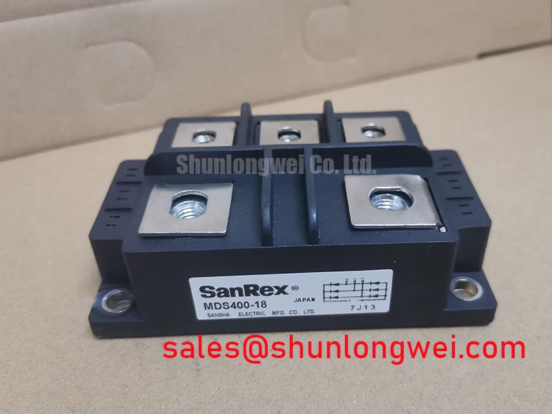
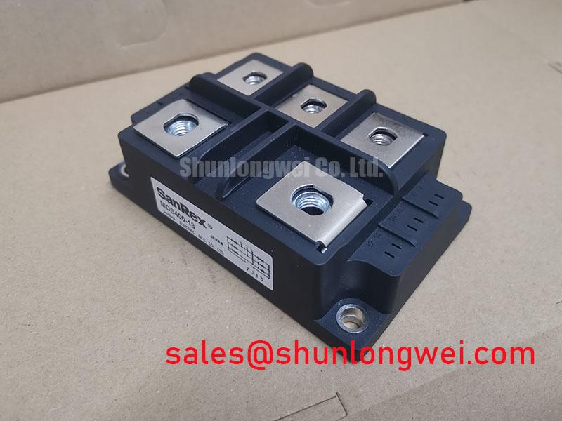
The MDS400-18 is a high-power three-phase diode bridge rectifier module rated at 1800V and 400A. It provides robust AC-to-DC rectification for demanding industrial systems. This module is a core building block in high-capacity power supplies and motor drive systems. It delivers reliable power conversion under continuous loads.
- Core Specifications: 1800V Peak Reverse Voltage ($V_{RRM}$) | 400A DC Output Current ($I_D$) | 2500V Isolation Voltage ($V_{isol}$)
- Engineering Benefits: The MDS400-18 minimizes forward voltage drop ($V_F$) to limit conduction losses, while the electrically isolated copper baseplate simplifies heatsink mounting.
- Application Fit: Engineers looking to design high-efficiency input stages will find that the module’s 400A rating provides a safe thermal margin in standard industrial three-phase line environments.
Download MDS400-18 Datasheet (PDF)
In-Depth Technical Analysis and Thermal Sizing
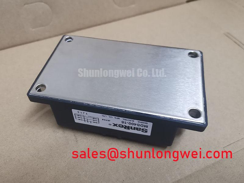
The performance of the MDS400-18 centers on its ability to handle thermal dissipation during continuous high-current rectification. Its internal diode chips are bonded to an isolated copper baseplate. This layout minimizes the junction-to-case Thermal Resistance ($R_{th(j-c)}$) to approximately 0.08°C/W per diode. Lower thermal resistance ensures that heat moves quickly from the silicon junction to the external heat dissipation system.

To understand thermal management, imagine thermal resistance as the constriction in a water pipe. A narrower constriction limits water flow. Similarly, a high thermal resistance value bottlenecks heat dissipation. The low $R_{th(j-c)}$ of this module acts as a wide, open pathway. It allows thermal energy to escape easily, keeping internal junctions within safe operating temperatures. This is critical during high-current surges.
In addition to thermal routing, this module belongs to our broader selection of power semiconductors. It features a non-repetitive surge forward current ($I_{FSM}$) rating of 5000A at a 10ms half-sine pulse. This surge capability protects the rectifier from circuit startup inrush currents. It also guards against transient load variations that occur in industrial utility grids.
Optimized Application Scenarios
The MDS400-18 is optimized for high-power industrial applications. It is suited for the following deployment scenarios:
- Variable Frequency Drives (VFDs): Serves as a reliable input rectifier stage, converting three-phase AC utility power into stable DC bus voltage.
- Industrial DC Power Supplies: Provides high DC output current with low ripple when integrated into switch-mode power supply (SMPS) pre-stages.
- Battery Charger Stations: Supports high-current fast-charging profiles for large battery banks and heavy material-handling vehicles.
- Electroplating Rectifiers: Delivers continuous, high-current DC power in chemically harsh environments thanks to its sealed, isolated package.
Best Fit Verdict: With an 1800V blocking voltage and 400A rating, this module is the ideal input rectifier for 380V to 480V industrial three-phase systems.
Key Specifications Parameter Table
Below are the verified electrical and thermal parameters for the MDS400-18 Power Module:
| Parameter Symbol | Technical Description | Value (Maximum/Typical) | Unit |
|---|---|---|---|
| $V_{RRM}$ | Repetitive Peak Reverse Voltage | 1800 | V |
| $I_D$ | Output Current (DC, Three-Phase) | 400 ($T_C = 100^circtext{C}$) | A |
| $I_{FSM}$ | Surge Forward Current (10ms half-sine) | 5000 | A |
| $V_{FM}$ | Peak Forward Voltage Drop (per diode at 400A) | 1.35 | V |
| $I_{RRM}$ | Repetitive Peak Reverse Current (at $V_{RRM}$) | 12 ($T_j = 150^circtext{C}$) | mA |
| $R_{th(j-c)}$ | Thermal Resistance (Junction to Case, Single Diode) | 0.08 | °C/W |
| $V_{isol}$ | RMS Isolation Voltage (AC, 1 minute) | 2500 | V |
For comparative sizing under alternative constraints, you can read our diode module parameters overview to check thermal differences between average and high-power packages.
Engineer’s FAQ
How do I calculate the heatsink requirements for the MDS400-18?
To calculate the required heatsink thermal resistance, you first need to determine the total power loss ($P_{loss}$). Calculate this by multiplying the forward voltage drop ($V_F approx 1.35text{V}$) by the average current flowing through each diode. Use the maximum junction temperature limit ($T_{j,max} = 150^circtext{C}$) and your peak ambient temperature to find the remaining thermal budget. For step-by-step calculations under industrial loads, reference our high-power rectification guide.
What is the purpose of the isolated baseplate in this rectifier?
The copper baseplate is internally isolated from the active silicon diode junctions. This allows you to mount the MDS400-18 onto a common metal heatsink alongside other semiconductor modules without causing an electrical short circuit. This configuration saves space and simplifies overall system design.
Is the MDS400-18 suitable for high-frequency rectification?
This module uses standard recovery diodes optimized for mains line frequency rectification (50Hz to 60Hz). It is not designed for high-frequency switch-mode rectification above 1kHz. Operating at high frequencies increases switching losses, leading to thermal overload.
Summary
The MDS400-18 three-phase bridge rectifier module combines high current output with excellent transient voltage tolerance. Its low conduction losses and highly efficient thermal design make it a reliable choice for heavy-duty industrial power systems. For technical inquiries, product validation assistance, or standard purchasing logistics, please contact our technical sales team.