An In-Depth Guide to the Infineon FF600R12ME4 EconoDUAL 3 1200V 600A Dual IGBT Module
FF600R12ME4 Infineon EconoDUAL 3 1200V 600A Dual IGBT Module
Introduction and Core Technical Highlights
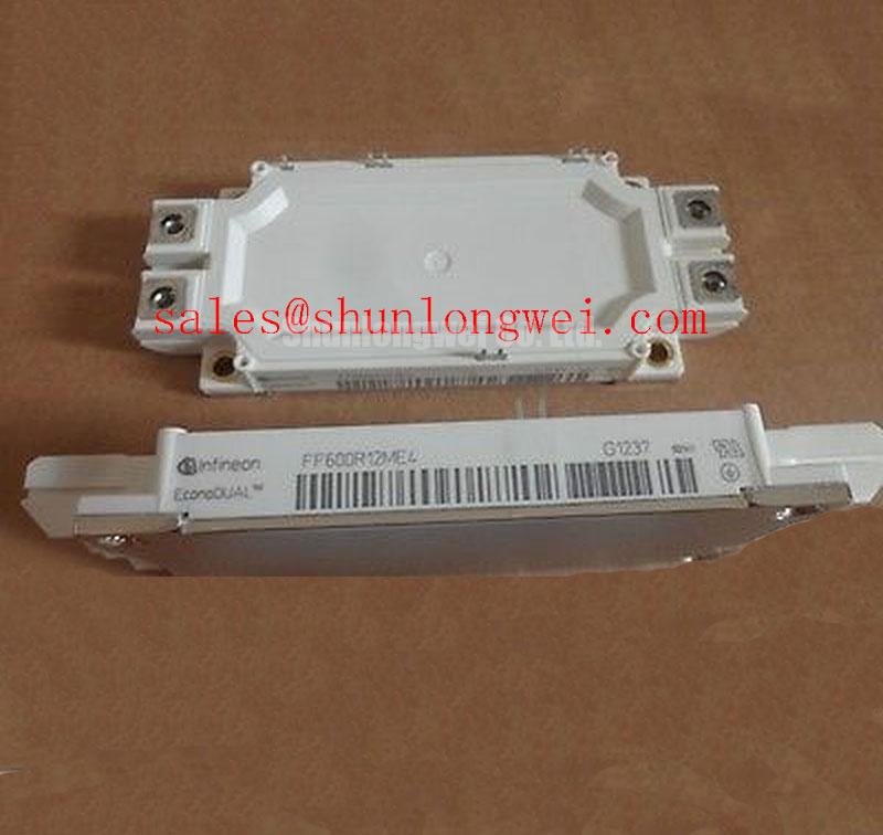
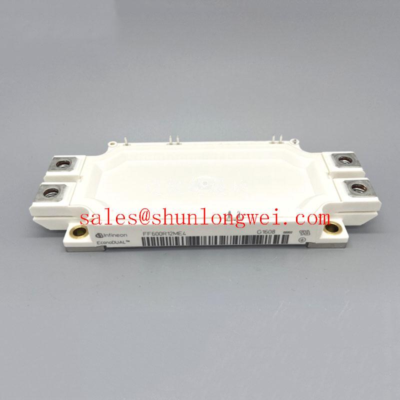
The FF600R12ME4 is an industry-standard dual IGBT Module developed by Infineon, housed in the widely utilized EconoDUAL™ 3 package. Engineered for medium-to-high power industrial switching applications, this module integrates fourth-generation trench-gate technology with an emitter-controlled diode. It provides an optimized combination of low conduction losses and rugged short-circuit capability, making it a reliable building block for half-bridge inverter topologies.
- Core Specifications: 1200V blocking voltage | 600A nominal collector current | 1.75V typical VCE(sat) at 125°C.
- Engineering Benefits: Low static losses reduce cooling package requirements, while the integrated thermistor simplifies thermal monitoring layout.
Download Official Infineon FF600R12ME4 Datasheet (PDF)

Technical Analysis and Engineering Value
The FF600R12ME4 utilizes Infineon’s Trenchstop™ IGBT4 technology. This architecture reduces the collector-emitter saturation voltage (VCE(sat)) to a typical value of 1.75V at nominal current. Lower saturation voltages directly translate to decreased conduction losses during the on-state period. For a detailed structural overview of this silicon generation, see our technical analysis on decoding IGBT4 technology.
Thermal management is optimized through an isolated copper baseplate, which ensures uniform heat distribution. You can think of thermal resistance (RthJC) as the physical width of a water pipe. A lower thermal resistance represents a wider pipe, allowing the heat generated by the silicon junctions to flow rapidly into the heatsink. This prevents localized thermal hotspots and thermal runaway.
Safe operation is further enhanced by an integrated NTC thermistor. Placed close to the IGBT chips, the NTC provides real-time temperature telemetry to the system controller. When pairing this module with a gate driver, engineers must calculate the appropriate gate resistors to balance turn-on overcurrents against high-voltage turn-off transients caused by stray parasitic inductance in the DC busbar.
Optimized Application Scenarios
- Variable Frequency Drives (VFDs): Ideal for industrial motor controllers because of the module’s high power cycling capability and low conduction overhead.
- Solar Inverters: High nominal current rating allows for compact central or multi-string inverter designs.
- Uninterruptible Power Supplies (UPS): Offers low switching losses, ensuring high efficiency in double-conversion online UPS systems.
- Wind Turbine Converters: Reliable half-bridge configuration supports multi-megawatt grid-tied generator systems.
The FF600R12ME4 is optimized for industrial 1200V converter designs operating up to 600A where conduction losses and integrated thermal monitoring are critical.
Key Specifications Parameter Table
| Symbol | Parameter Description | Value / Rating | Unit |
|---|---|---|---|
| VCES | Collector-Emitter Voltage (Tvj = 25°C) | 1200 | V |
| IC nom | Nominal Collector Current (TC = 100°C) | 600 | A |
| VCE(sat) | Collector-Emitter Saturation Voltage (IC = 600A, Tvj = 125°C) | 1.75 (typ) / 2.10 (max) | V |
| VGES | Gate-Emitter Peak Voltage | +/- 20 | V |
| tsc | Short-Circuit Withstand Time (VGE ≤ 15V, VCC = 800V, Tvj ≤ 150°C) | 10 | μs |
| RthJC | Thermal Resistance, Junction to Case (per IGBT) | 0.060 | K/W |
Engineers’ Frequently Asked Questions
Q1: What are the layout considerations to minimize voltage spikes with the FF600R12ME4?
A1: High-power switching generates significant voltage overshoots due to loop inductance. Engineers must place low-ESR snubber capacitors directly across the DC terminals and design a laminated, low-inductance busbar to keep parasitic loop inductance below 20 nH.
Q2: Can the integrated NTC thermistor be used for direct overtemperature shutdown?
A2: The internal NTC is highly accurate for static temperature monitoring but has a thermal time constant delay relative to the actual silicon junction. It must be used for system-level thermal management and slow overload protection, not for instantaneous short-circuit thermal shutdown.
Q3: What is the recommended gate driver voltage for the FF600R12ME4?
A3: For optimal performance and conduction loss minimization, a turn-on gate voltage of +15V is recommended. To ensure robust noise immunity and prevent parasitic turn-on, a negative turn-off gate voltage of -8V to -15V should be applied.
The Infineon FF600R12ME4 provides a standardized, high-power density solution for demanding converter topologies. Combining Trenchstop™ IGBT4 technology with EconoDUAL™ packaging, it delivers predictable electrical performance and robust thermal endurance to support your power system designs.