Fuji Electric 2MBI450VE-120-50 1200V 450A Dual IGBT Module: Features and Specifications
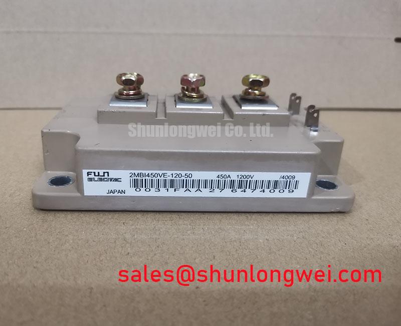
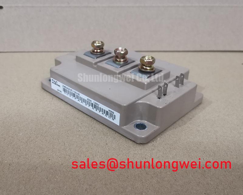
Fuji Electric 2MBI450VE-120-50 | 1200V 450A Dual IGBT Module
The Fuji Electric 2MBI450VE-120-50 is a high-power dual-channel module designed within the V-Series semiconductor family. It utilizes advanced trench-gate and field-stop technologies to balance conduction efficiency and switching dynamics. Engineered for high-power industrial power conversion, this module delivers robust electrical isolation and low thermal resistance.
- Core Ratings: 1200V | 450A Continuous DC ($T_C = 80^circtext{C}$)
- Conduction Efficiency: $V_{CE(sat)}$ of only 1.90V typical at rated current and $T_j = 125^circtext{C}$
- Thermal Integrity: Low internal thermal resistance paired with premium isolated baseplates for enhanced power cycling capability
For complete static curves, dynamic switching times, and safe operating limits, download the technical datasheet below.
Download Official Datasheet (PDF)

Unlocking Thermal and Electrical Performance with V-Series Tech
The 2MBI450VE-120-50 module implements Fuji’s V-Series trench gate architecture. This structural optimization minimizes the collector-emitter saturation voltage ($V_{CE(sat)}$). Conduction loss ($V_{CE(sat)}$) is analogous to a narrow toll booth on a busy highway. A lower toll allows electrical current to pass through with reduced resistance. This decreases energy wasted as heat during heavy continuous loads.
Minimizing thermal resistance is vital when managing high current densities. The 2MBI450VE-120-50 achieves a low junction-to-case thermal resistance ($R_{th(j-c)}$) of 0.060 $^circtext{C}/text{W}$ for the IGBT section. This low resistance ensures that heat moves rapidly away from the silicon die. Lowering operating temperatures directly improves power cycling lifetime and mitigates thermal stress.
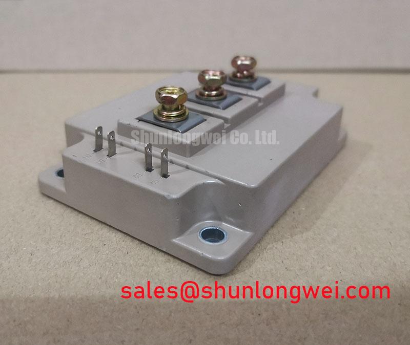
In high-frequency applications, circuit designers must address package-level layout constraints. The terminal arrangement of the 2MBI450VE-120-50 is engineered to reduce parasitic inductance. Minimizing parasitic inductance suppresses transient voltage spikes ($V = L cdot frac{di}{dt}$) during rapid turn-off phases. Consequently, this simplifies snubber circuit designs and reduces switching losses.
Optimized Industrial Applications
The electrical and thermal characteristics of the 2MBI450VE-120-50 make it highly suited for several demanding industrial systems:
- Variable Frequency Drives (VFDs): Low conduction losses optimize energy efficiency during continuous variable-torque operations.
- Solar Inverters: High voltage ratings and excellent thermal performance support stable, grid-tied power delivery under varying load curves.
- Uninterruptible Power Supplies (UPS): Rapid, reliable switching characteristics ensure seamless power transfer without compromising thermal margins.
Best Match: Industrial motor drives and grid-tied inverters needing stable, high-current switching under $150^circtext{C}$ maximum junction conditions.
Key Specifications Parameter Table
The technical parameters below represent verified values from the official manufacturer datasheet:
| Parameter | Symbol | Value / Rating | Unit |
|---|---|---|---|
| Absolute Maximum Ratings ($T_C = 25^circtext{C}$ unless noted) | |||
| Collector-Emitter Voltage | $V_{CES}$ | 1200 | V |
| Gate-Emitter Voltage | $V_{GES}$ | $pm 20$ | V |
| Continuous Collector Current ($T_C = 80^circtext{C}$) | $I_C$ | 450 | A |
| Pulsed Collector Current (1ms) | $I_{CP}$ | 900 | A |
| Isolation Voltage (AC 1 min) | $V_{isol}$ | 2500 | V |
| Electrical Characteristics (Typical at $T_j = 125^circtext{C}$) | |||
| Collector-Emitter Saturation Voltage | $V_{CE(sat)}$ | 1.90 | V |
| Gate-Emitter Threshold Voltage | $V_{GE(th)}$ | 6.5 | V |
| Thermal Characteristics | |||
| Thermal Resistance (IGBT, junction to case) | $R_{th(j-c)}$ | 0.060 (Max) | $^circtext{C}/text{W}$ |
Engineer FAQ
What is the benefit of the V-Series trench gate in the 2MBI450VE-120-50?
The V-Series trench gate structure increases channel density. This reduces the internal conduction resistance, lowering $V_{CE(sat)}$ to 1.90V under high-load conditions. As a result, static power loss is minimized during continuous operation.
How do we calculate thermal margins for the 2MBI450VE-120-50 under 450A load?
Using the maximum $R_{th(j-c)}$ of 0.060 $^circtext{C}/text{W}$, multiply the power dissipation by the thermal resistance to determine the junction-to-case temperature delta. Ensure the mounting surface has a high-quality thermal interface material (TIM) to prevent localized hotspots.
What mounting torque is recommended for the power terminals and mounting holes?
To avoid housing fractures and high contact resistance, follow the datasheet guidelines. The module typically requires M5 screws for the mounting layout and M6 screws for the power terminals. Correct torque prevents physical stress on the internal copper wire bonds.
The Fuji Electric 2MBI450VE-120-50 represents a balanced solution in the power semiconductors market. It offers robust 1200V/450A capability with low conduction losses. Its design addresses the strict thermal and electrical challenges faced by system engineers. The module supports stable operation across diverse industrial power conversion designs.