Fuji 6MBI15GS-060 600V 15A Six-Pack IGBT Module: Technical Overview and Application Guide
Fuji 6MBI15GS-060 600V 15A Six-Pack IGBT Module
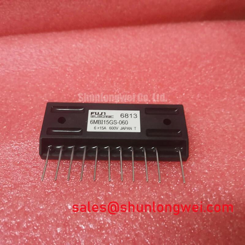
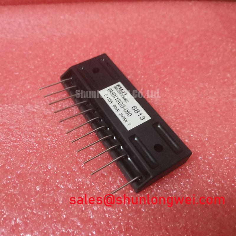
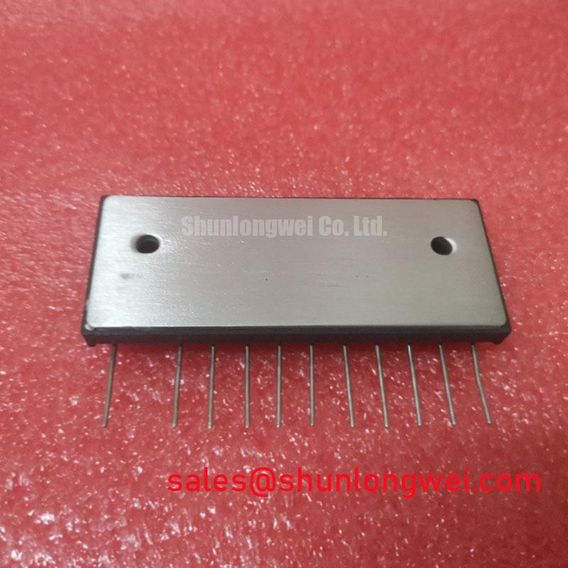
The 6MBI15GS-060 is an authentic six-pack IGBT module manufactured by Fuji Electric for compact three-phase inverter applications. It integrates six low-loss IGBT switches and matching fast-recovery freewheeling diodes on an isolated copper baseplate. This architecture delivers balanced dynamic switching and robust thermal performance in space-constrained industrial equipment.
- Core Ratings: 600V | 15A continuous collector current ($I_C$) | 60W maximum power dissipation per switch
- Engineering Advantages: Low collector-emitter saturation voltage ($V_{CE(sat)}$) and optimized switching behavior that simplifies driver integration.
- Design Intent: Delivers an all-in-one three-phase bridge that reduces assembly layout complexity compared to discrete solutions.
Technical Analysis and Engineering Architecture
The 6MBI15GS-060 achieves high conversion efficiency through optimized planar gate silicon cells paired with low-forward-drop antiparallel diodes. Operating at a typical saturation voltage ($V_{CE(sat)}$) of 2.1V at 15A, the module restricts conduction losses during continuous inverter operation. In addition, symmetric internal layout minimizes stray terminal inductance, which helps restrain voltage spikes during high-frequency commutations.
Think of thermal resistance like the width of a drainage pipe; a lower thermal impedance allows operational heat to escape rapidly into the heatsink. The junction-to-case thermal resistance ($R_{th(j-c)}$) of 2.08°C/W per IGBT ensures the die remains within the maximum junction temperature rating of +150°C even under rapid thermal cycling.
For design engineers evaluating PIM vs discrete IGBT implementations, this integrated 6-pack setup provides consistent parameter matching across all six internal switches. Implementing an adequate gate drive design ensures stable gate turn-off behavior within the rated Safe Operating Area (SOA).
Target Application Scenarios
- Compact Variable Frequency Drive (VFD) Stages: Integrates full 3-phase output stages in low-power industrial motor drives.
- AC Servo Amplifiers: Offers low dynamic losses and rapid switching response for precision motion actuators.
- Uninterruptible Power Supplies (UPS): Serves as an efficient 3-phase inversion stage for auxiliary backup power units.
- Industrial Robotics & Pumps: Direct PCB pin integration reduces cabinet space in multi-axis automation controllers.
The 6MBI15GS-060 delivers dependable 600V switching for compact sub-2.2kW three-phase drive platforms requiring isolated, integrated package architectures.
Key Specifications Table
| Parameter | Symbol | Test Conditions / Rating | Unit |
|---|---|---|---|
| Collector-Emitter Voltage | $V_{CES}$ | $V_{GE} = 0text{V}, T_j = 25^circtext{C}$ | 600 V |
| Continuous Collector Current | $I_C$ | $T_c = 25^circtext{C}$ (15A continuous) | 15 A |
| Pulsed Collector Current | $I_{CP}$ | $1text{ms}$ Pulse | 30 A |
| Collector Power Dissipation (per switch) | $P_C$ | $T_c = 25^circtext{C}$ | 60 W |
| Collector-Emitter Saturation Voltage | $V_{CE(sat)}$ | $I_C = 15text{A}, V_{GE} = 15text{V}, T_j = 25^circtext{C}$ (Typ. 2.1V) | 2.7 (Max) V |
| Diode Forward Voltage | $V_F$ | $I_F = 15text{A}, V_{GE} = 0text{V}$ | 2.5 (Max) V |
| Thermal Resistance (IGBT Junction-to-Case) | $R_{th(j-c)}$ | Per single IGBT switch | 2.08 °C/W |
| Isolation Voltage | $V_{isol}$ | AC 1 min, baseplate to terminal | 2500 V |
Engineering FAQ
Q1: What gate driving voltage is recommended for the 6MBI15GS-060?
A: A gate voltage ($V_{GE}$) of +15V is recommended for turn-on to ensure the device reaches its specified low $V_{CE(sat)}$. A negative bias or active pull-down during turn-off prevents unintended dv/dt-induced shoot-through.
Q2: How does this device compare to other low-loss modules like the 6MBI15LS-060?
A: While both are 600V/15A modules, the LS series optimizes switching speed characteristics, whereas the GS series provides a balanced trade-off between conduction drops and rugged safe operating margins. Refer to the 6MBI15LS-060 technical review for comparative data.
Q3: What thermal interface precautions are critical during mounting?
A: Apply a uniform thermal grease layer (50–100µm thickness) across the baseplate before fastening. Uneven mounting or improper torque can induce mechanical strain or local overheating, which is analyzed in detail in our review of IGBT failure mechanisms.
Reliability and Integration Summary
The Fuji 6MBI15GS-060 provides power system designers with a compact, electrically isolated six-pack configuration in the 600V class. Engineers seeking verified specifications, replacement options, or component procurement for power electronic stages can explore related solutions within our specialized power semiconductors catalog.