Mitsubishi PM150RSE120: 1200V 150A Intelligent Power Module Technical Overview and Applications
PM150RSE120 Mitsubishi 1200V 150A Intelligent Power Module
Product Overview & Core Highlights
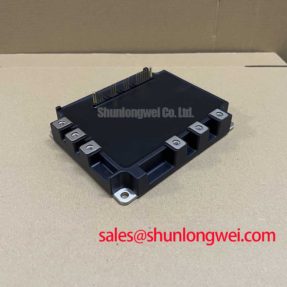
The PM150RSE120 is an industrial-grade, 3-phase 1200V/150A IPM (Intelligent Power Module) with an integrated dynamic brake circuit. Built for 400V/480V class AC motor inverter systems, it incorporates matched gate drive stages, comprehensive fault diagnostics, and low-loss switching silicon inside a single isolated baseplate package.

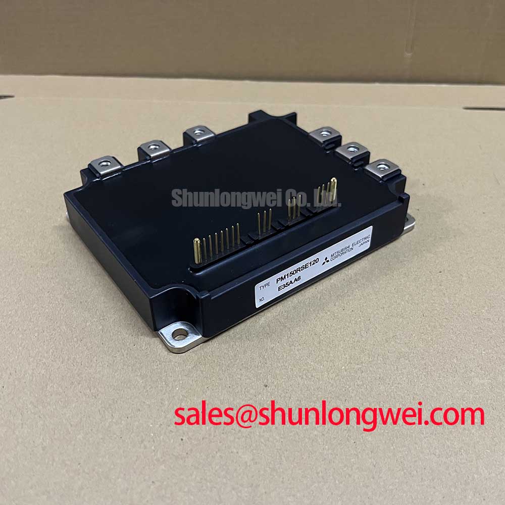
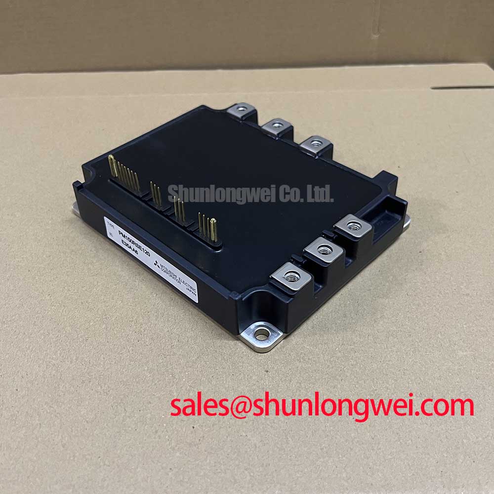
- Core Ratings: 1200V collector-emitter voltage ($V_{CES}$), 150A continuous inverter collector current ($I_C$), and 2500V AC isolation rating for 1 minute.
- Integrated Inverter + Brake Topology: 6-pack inverter configuration plus an independent 50A brake chopper switch in an R-series package.
- On-Chip Diagnostic Intelligence: Real-time protection against short-circuits (SC), overtemperature (OT), and control-supply under-voltage lockout (UVLO).
Technical Architecture & UVP Analysis
The primary Unique Value Proposition (UVP) of the PM150RSE120 is its unified high-voltage power stage and low-latency drive integration. In traditional discrete or conventional inverter designs, lengthy PCB traces between external gate drivers and IGBT gates introduce parasitic inductance, generating severe ringing and spurious turn-ons during high-speed $di/dt$ transitions. By housing custom drive ICs directly adjacent to the silicon dies, the module mitigates gate ringing and guarantees switching synchronization across all 6 inverter arms.
Consider the module’s internal drive architecture like dedicated on-site traffic marshals at every intersection rather than a remote dispatcher miles away. Because the control loop operates locally within millivolts and nanoseconds, overcurrent situations trigger a controlled soft shut-down directly at the gate. This eliminates destructive voltage spikes ($V = L times di/dt$) without requiring oversized snubber networks.
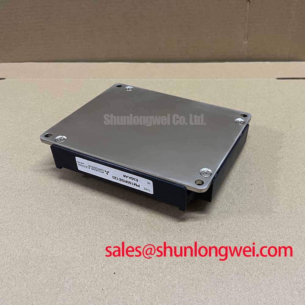
Thermal management is further reinforced via its direct-bonded copper (DBC) substrate. A low junction-to-case thermal resistance ($R_{th(j-c)} le 0.15^circtext{C/W}$ per inverter IGBT) allows steady power dissipation ($P_c = 830text{W}$) under continuous dynamic loads, delivering proven hardware reliability in heavy-duty power semiconductors applications.

Target Application Scenarios
- Industrial Variable Frequency Drives (VFD): Designed for 15kW to 22kW motor drives running from 380V–480V three-phase utility lines.
- AC Servo Amplifiers & Motion Systems: High-bandwidth PWM switching capability provides smooth torque response for CNC machining and automated material handling.
- Regenerative Braking Systems: The dedicated brake IGBT provides immediate overvoltage dissipation during motor deceleration without external chopping modules.
- Uninterruptible Power Supplies (UPS): Three-phase PWM bridge conversion maintains clean sinusoidal AC waveforms under variable non-linear loading.
The PM150RSE120 is the ideal power solution for high-reliability 400V-class industrial inverters requiring integrated braking and fault-immune protection.
Key Specifications Parameter Table
| Parameter Category | Symbol / Parameter | Ratings / Values | Unit |
|---|---|---|---|
| Inverter Power Part | Collector-Emitter Voltage ($V_{CES}$) | 1200 | V |
| Collector Current Continuous ($I_C, T_C = 25^circtext{C}$) | 150 (Peak: 300) | A | |
| Collector Dissipation ($P_C$ per switch) | 830 | W | |
| Brake Chopper Part | Brake Collector Current ($I_C$) | 50 (Peak: 100) | A |
| Brake Diode DC Current ($I_F$) | 50 | A | |
| Control & Isolation | Control Supply Voltage ($V_D$) | 15.0 (Nominal: 13.5 to 16.5) | V |
| Isolation Voltage ($V_{iso}$, 60Hz Sinusoidal, 1 min) | 2500 | Vrms | |
| Operating Junction Temperature ($T_j$) | -20 to +150 | °C |
Engineering FAQ
Q1: What are the recommended optocoupler requirements for driving the PM150RSE120 control pins?
A1: High-speed optocouplers with high Common-Mode Transient Immunity (CMTI ≥ 10 kV/μs) and propagation delay times under 0.8 μs are recommended to ensure clean edge transitions and prevent false triggering during switching transients.
Q2: How should thermal interface material (TIM) be applied to the PM150RSE120 baseplate?
A2: Apply a uniform layer of thermal grease with a thickness of 100 μm to 150 μm across the entire copper baseplate. Tighten mounting screws in two stages to the specified torque of 2.5–3.5 N·m to avoid substrate warpage and minimize contact thermal resistance.
Q3: How does the PM150RSE120 behave when an over-temperature (OT) fault occurs?
A3: When the internal baseplate temperature exceeds the trip threshold ($110^circtext{C}$ to $125^circtext{C}$), the module disables the gate drive outputs and asserts an active-low Fault signal ($F_o$) to the system microcontroller until the thermal condition drops below the reset level.
Q4: Can the PM150RSE120 directly replace a PM100RSE120 in existing motor drive hardware?
A4: Both devices share the same package form factor, pinout, and 1200V rating. However, the higher current capacity (150A vs 100A) of the PM150RSE120 requires confirming that DC bus capacitance, heatsink thermal dissipation capacity, and busbar ampacity can accommodate the increased output current.
Application Note & System Integration
Implementing the PM150RSE120 in modern three-phase motor converters streamlines circuit board layouts by consolidating gate drive bias circuits, short-circuit current monitoring, and dynamic brake control into a rugged package. Exploring the IPM advantage in power electronics provides essential layout best practices to maximize signal integrity and power conversion efficiency across demanding industrial operating environments.