BTA25-700B 25A 700V Isolated TRIAC: Technical Specifications, Thermal Performance, and Applications
BTA25-700B STMicroelectronics 25A 700V Isolated TRIAC
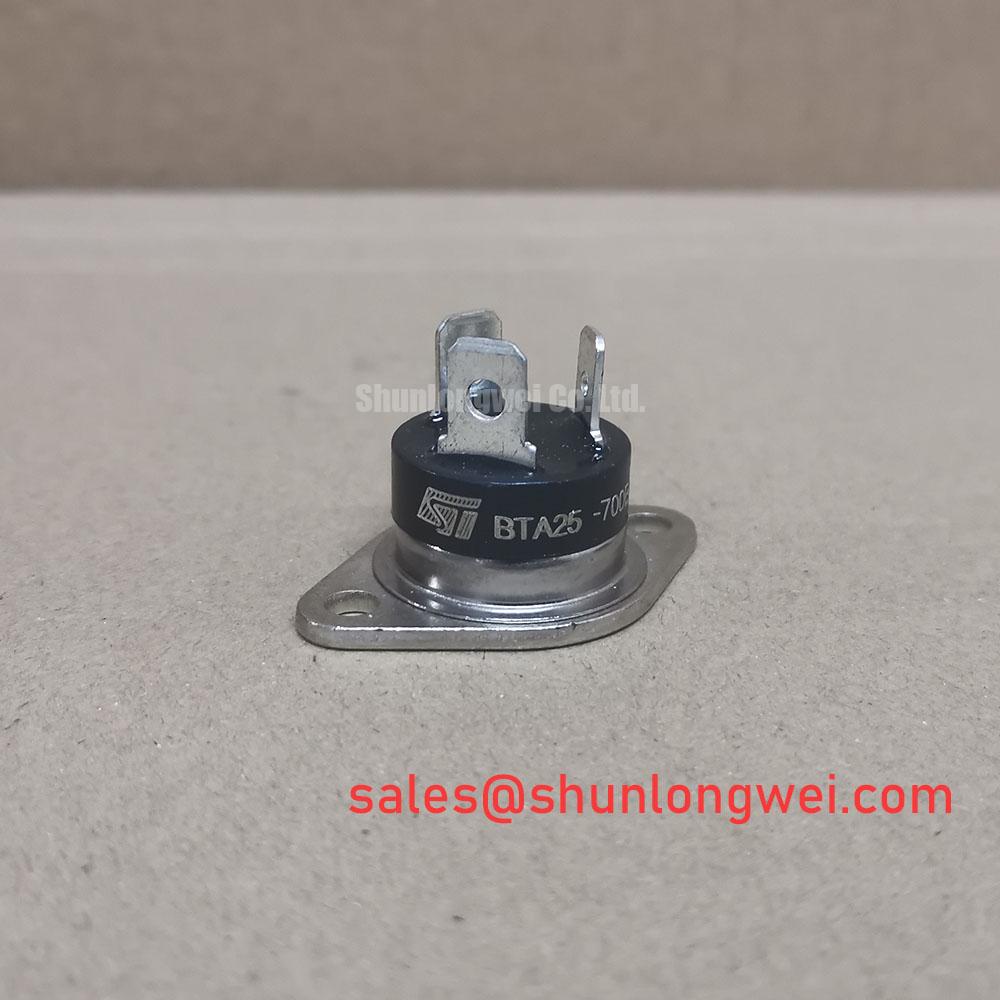
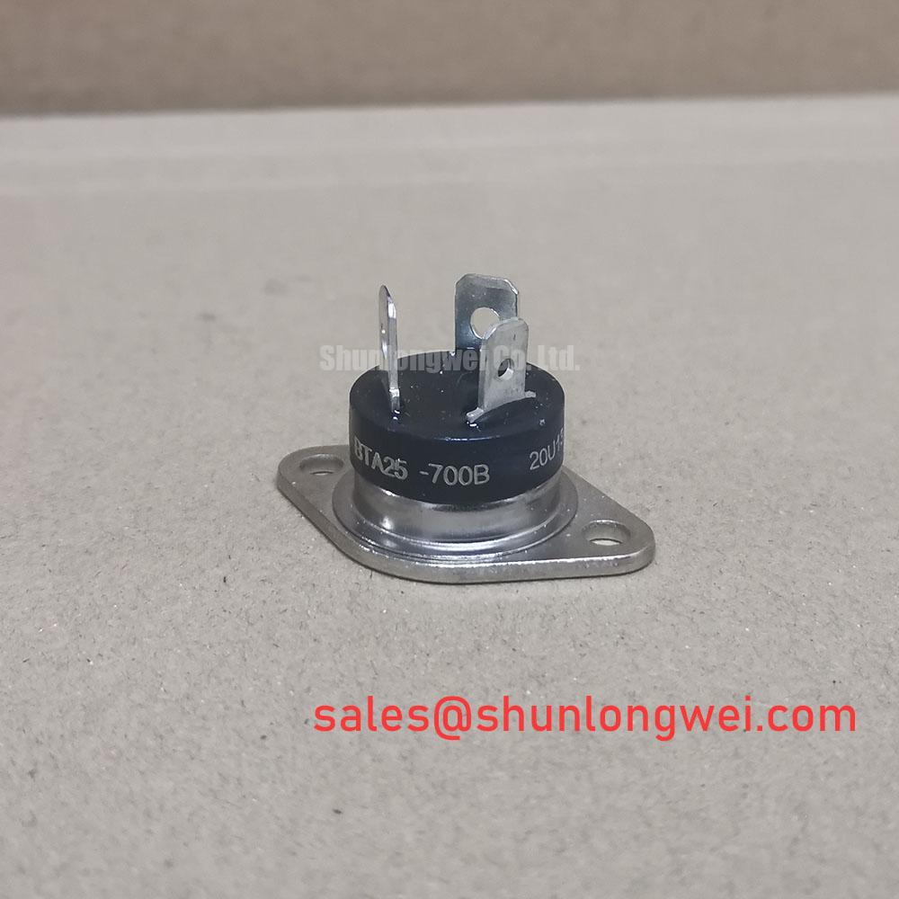
Product Overview and Core Engineering Value
The BTA25-700B is a high-current bidirectional AC silicon switch housed in an electrically isolated TOP3 package. It delivers high thermal dissipation efficiency combined with an internal 2500V RMS dielectric isolation barrier, eliminating external insulation hardware in compact power designs.
- Core Ratings: 700V $V_{DRM}/V_{RRM}$ | 25A $I_{T(RMS)}$ | 50mA $I_{GT}$ (Quadrants I–III)
- Key Advantage: Integrated ceramic tab isolation reduces assembly complexity and simplifies heatsink grounding.
- Surge Handling: 250A non-repetitive peak surge current rating ($I_{TSM}$ at 50Hz) provides rugged transient withstand.
For technical baseline parameters, engineers can review the official STMicroelectronics documentation when sizing protection networks in power semiconductors assemblies.
Technical Analysis: Commutation Ruggedness and Thermal Dissipation
Operating high-inductive loads with bidirectional thyristors presents turn-off challenges due to high $dI/dt$ and transient voltage spikes ($dV/dt$). The BTA25-700B features a critical rate of off-state voltage rise ($dV/dt$) specified at a minimum of 500 V/µs at $T_j = 125^circtext{C}$. This capability limits spurious re-triggering during rapid voltage transitions across main terminals A1 and A2.
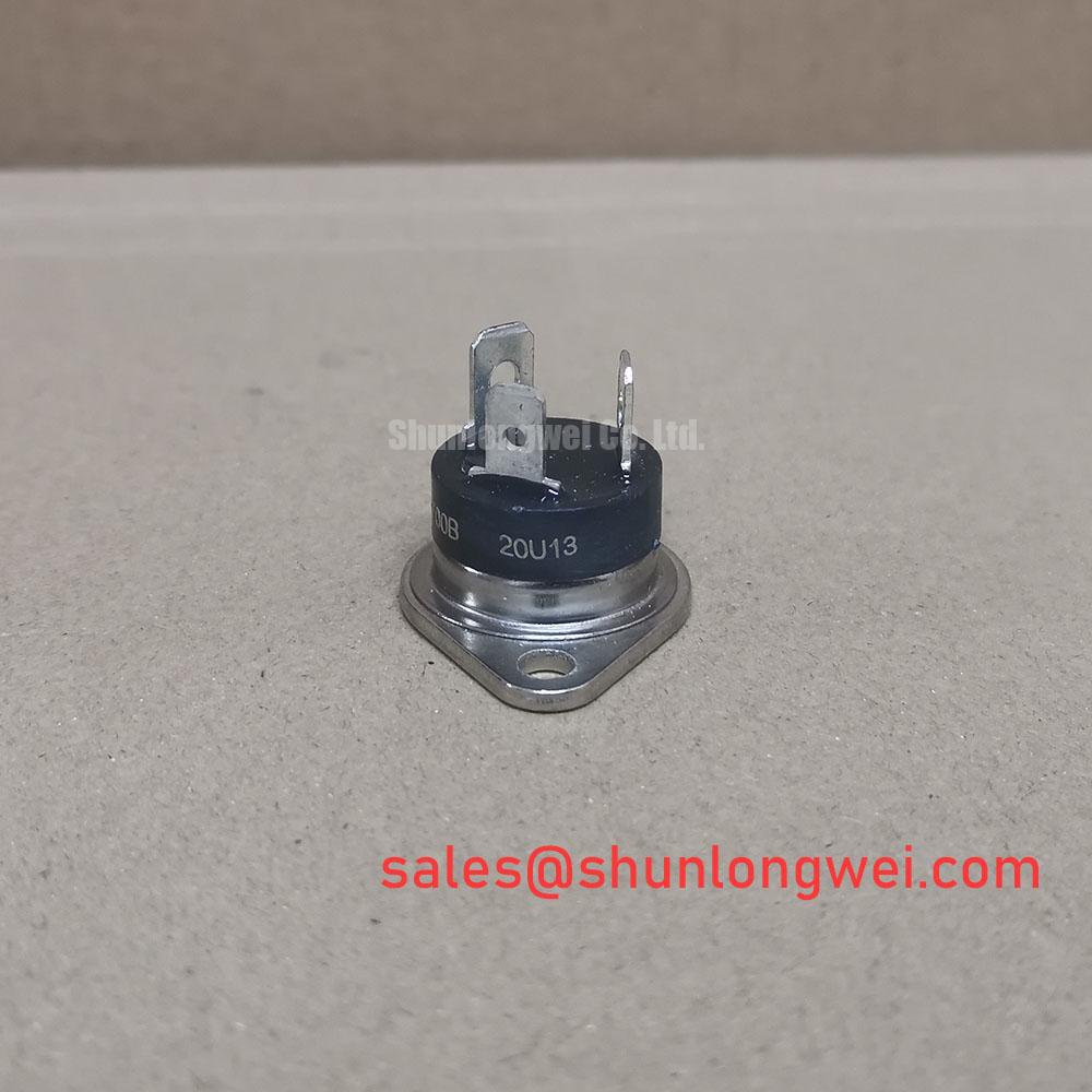
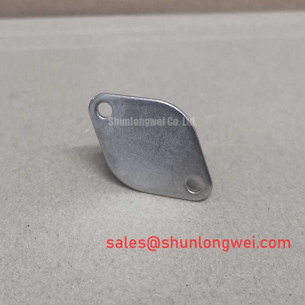
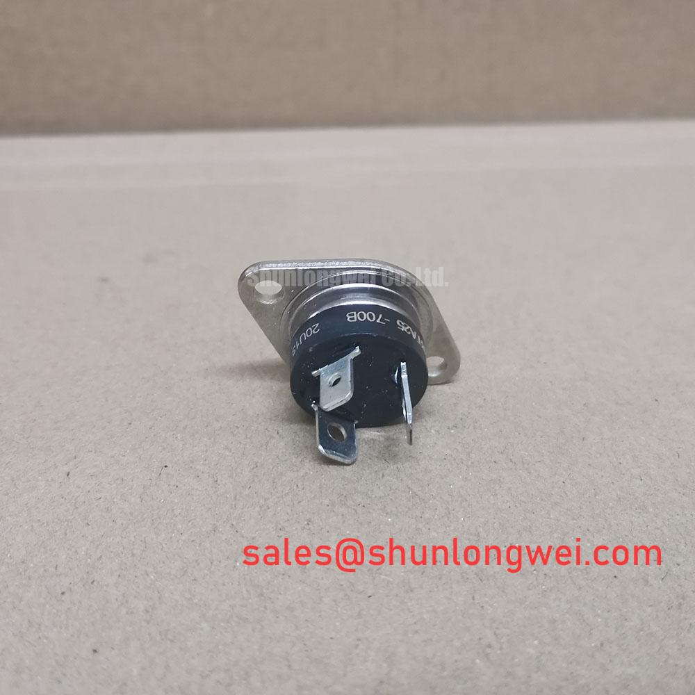
The package architecture utilizes internal ceramic bonding to isolate the active silicon die from the copper mounting baseplate. One can visualize the junction-to-case thermal resistance ($R_{th(j-c)}$) as the diameter of an exhaust pipe: at 1.0 °C/W for AC conduction, thermal energy escapes swiftly into the heatsink without requiring extra mica insulators that would otherwise choke heat transfer.
Compared to standard non-insulated devices, this internal ceramic isolation design reduces thermal stacking penalties and lowers the risks associated with dielectric puncture during industrial line disturbances.
Optimized Application Scenarios
- Solid-State Relays (SSRs): Delivers 25A continuous line handling with direct multi-device mounting onto a shared heatsink chassis in modern solid-state relay topologies.
- Industrial Induction Motor Starters: Withstands heavy rotor inrush currents through its 250A $I_{TSM}$ capacity.
- High-Power Heating Controls: Controls multi-kilowatt resistive loads with low on-state voltage drop ($V_{TM} le 1.55text{V}$ at 35A peak).
- Phase-Angle Power Controllers: Handles quadrant I to III gating reliably via standard 50mA trigger circuits.
The BTA25-700B offers an optimal balance between 2500V galvanic tab isolation and low thermal resistance for 230V/400V mains power control.
Key Electrical & Thermal Specifications
| Parameter | Symbol | Test Conditions / Value | Unit |
|---|---|---|---|
| Repetitive Peak Off-State Voltage | $V_{DRM}, V_{RRM}$ | $T_j = 125^circtext{C}$ / 700 | V |
| RMS On-State Current (Full Sine) | $I_{T(RMS)}$ | $T_c = 75^circtext{C}$ / 25 | A |
| Non-Repetitive Peak Surge Current | $I_{TSM}$ | $t_p = 20text{ms}$ (50Hz), $T_j text{ initial} = 25^circtext{C}$ / 250 | A |
| $I^2t$ Value for Fusing | $I^2t$ | $t_p = 10text{ms}$ / 310 | $A^2s$ |
| Gate Trigger Current (Q1–Q3) | $I_{GT}$ | $V_D = 12text{V}, R_L = 33Omega, T_j = 25^circtext{C}$ / Max 50 | mA |
| Peak On-State Voltage Drop | $V_{TM}$ | $I_{TM} = 35text{A}, t_p = 380mutext{s}, T_j = 25^circtext{C}$ / Max 1.55 | V |
| Critical Rate of Voltage Rise | $dV/dt$ | $V_D = 67% V_{DRM}$, Gate open, $T_j = 125^circtext{C}$ / Min 500 | V/µs |
| Thermal Resistance (Junction to Case) | $R_{th(j-c)}$ | Full cycle AC conduction / 1.0 | °C/W |
| RMS Insulation Voltage | $V_{INS}$ | 1 minute, 50Hz / 2500 | V |
Engineering FAQ
Q1: What snubber configuration is required when switching inductive loads with the BTA25-700B?
Because the BTA25-700B is a standard four-quadrant structure (B-grade sensitivity), an RC snubber circuit (typically 100nF in series with 47Ω to 100Ω) across terminals A1 and A2 is recommended to damp high $(dI/dt)_c$ and prevent premature commutation triggering.
Q2: How should semiconductor protection fuses be selected for this device?
Fuses must clear before the thyristor junction exceeds its melting limits. The total clearing $I^2t$ of the selected high-speed fuse must remain strictly below the TRIAC’s rated $I^2t$ of 310 $A^2s$ at 10ms, as outlined in guides to I²t fuse coordination.
Q3: Can the TOP3 tab be mounted directly to an earthed metal enclosure?
Yes. The BTA version provides internal ceramic insulation rated for 2500V RMS. It requires only thermal interface material between the metal tab and the heatsink, without external insulating washers or silicone pads.
Q4: What is the recommended gate drive current for reliable turn-on across operating temperatures?
While the maximum specified trigger current ($I_{GT}$) is 50mA at $25^circtext{C}$, gate drive circuits should deliver a pulse amplitude of 2 to 3 times $I_{GT}$ (100mA to 150mA) with a fast rise time ($< 1mutext{s}$) to achieve uniform conduction across all active die areas.
Application Summary
The BTA25-700B provides a verified, robust solution for AC line power switching up to 25A. Its 2500V RMS isolated TOP3 package, 700V peak blocking voltage, and low thermal impedance streamline mechanical layout and ensure consistent operation in heavy-duty industrial and commercial switching systems.