Mitsubishi PM450CG1C065 Intelligent Power Module: Technical Architecture, Specifications, and Applications
PM450CG1C065 Mitsubishi Intelligent Power Module (IPM)
M2: Technical Overview and Core Architecture
The Mitsubishi PM450CG1C065 is a high-power Intelligent Power Module (IPM) engineered for high-efficiency three-phase power switching applications. Incorporating advanced 5th-generation planar/CSTBT silicon technology alongside built-in gate drive circuitry and comprehensive protection networks, the module delivers exceptional power density with minimal switching and conduction losses.
- Core Ratings: 650V Collector-Emitter Voltage ($V_{CES}$), 450A Continuous Collector Current ($I_C$), Low $V_{CE(sat)}$.
- Engineering Advantages: Reduces thermal heatsink overhead, eliminates external gate driver design complexity, and integrates direct fault feedback.
- Design Objective: Simplifies hardware layouts in high-current low-voltage three-phase motor drives and distributed industrial systems requiring fast switching up to 20kHz.
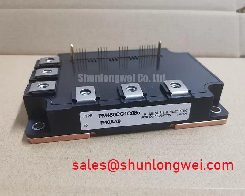

M3: Engineering Analysis: Electrical & Thermal Dynamics
The PM450CG1C065 integrates dedicated gate drive circuits matched precisely to the internal IGBT chips. This integration eliminates the parasitic trace inductance typically found between discrete gate drivers and switches, effectively suppressing high $dv/dt$ induced Miller transients without requiring external negative gate bias supplies. Engineers can consult further details regarding protection mechanisms in our analysis of the IPM advantage and integrated architecture.
Thermal management is supported by an electrically isolated baseplate featuring low junction-to-case thermal impedance ($R_{th(j-c)}$). Thermal resistance operates like the diameter of a plumbing pipe: lower values allow thermal energy to flow rapidly away from the die into the heatsink, keeping internal junction temperatures well below the absolute maximum of 150°C during heavy continuous loads.


Integrated real-time protection includes short-circuit current limiting (SC), control power supply under-voltage lockout (UV), and over-temperature detection (OT) with dedicated fault output signaling ($F_o$). These autonomous safety features respond within microseconds, preventing destructive thermal runaway even under sudden phase faults or load short-circuits. More about fault mitigation can be seen in our article on preventing IGBT burnout via under-voltage lockout.
M4: Optimized Application Environments
- Industrial Variable Frequency Drives (VFD): Handles high RMS phase currents for 200V/240V AC motor control due to its 450A collector rating.
- Uninterruptible Power Supplies (UPS): Fast switching capability minimizes output harmonic distortion and filtering component sizes.
- Servo Drive Systems: Low switching loss enables higher PWM carrier frequencies, improving dynamic torque response in automated machinery.
- Low-Voltage Renewable Energy Inverters: Ideal for battery-backed energy storage conversions with DC-bus levels up to 400V–450V.
Best match: High-density 200V-class industrial inverters needing 450A capacity with fully integrated protection and minimal thermal footprint.
M5: Critical Specification Parameters
| Mitsubishi PM450CG1C065 Datasheet Ratings ($T_j = 25^circtext{C}$ unless noted) | |||
|---|---|---|---|
| Category | Parameter / Symbol | Rating / Value | Unit |
| Absolute Maximum Ratings | Collector-Emitter Voltage ($V_{CES}$) | 650 | V |
| Collector Current, Continuous ($I_C$) | 450 | A | |
| Collector Current, Peak ($I_{CP}$) | 900 | A | |
| Maximum Junction Temperature ($T_{j(max)}$) | +150 | °C | |
| Electrical Characteristics | Collector-Emitter Saturation Voltage ($V_{CE(sat)}$, Typ.) | 1.75 | V |
| Control Supply Voltage ($V_D$) | 13.5 to 16.5 | V | |
| Switching Times ($t_{on} / t_{off}$, Typ.) | 0.8 / 2.3 | µs | |
| Thermal & Isolation | Thermal Resistance, Junction-to-Case ($R_{th(j-c)}$ per IGBT) | 0.08 | K/W |
| Isolation Voltage ($V_{iso}$, 60Hz, AC 1 min) | 2500 | Vrms | |
M6: Technical FAQ
Q1: What is the optimal control supply voltage ($V_D$) for the internal gate driver of the PM450CG1C065?
A1: The recommended control voltage is 15V (operating range: 13.5V to 16.5V). Operating below 13.5V may trigger the built-in under-voltage (UV) protection circuit and disable switching output.
Q2: How should external DC-link bypass capacitance be configured to manage turn-off voltage spikes?
A2: Due to the high 450A current rating and fast switching speed, low-inductance busbars combined with a high-frequency snubber capacitor placed directly across the P-N power terminals are necessary to clamp inductive voltage overshoot.
Q3: Does this module require isolated power supplies for all control channels?
A3: Yes, standard 3-phase IPM topologies require four isolated power supplies: three independent floating supplies for the upper-arm phases ($U, V, W$) and one shared supply for the lower-arm control circuitry.
M7: Structural Integration Summary
The Mitsubishi PM450CG1C065 delivers an integrated 650V/450A six-pack switching platform that eliminates the need for separate gate drive PCBs and discrete protection circuits. Its balanced thermal performance and internal protection systems make it a dependable building block for compact, high-reliability industrial power converters.