A Technical Analysis of the Toshiba MIG75J6CSB1W IPM
MIG75J6CSB1W Toshiba 600V 75A IGBT IPM Technical Analysis
Integrated 6-in-1 IPM for Compact Three-Phase Motor Control
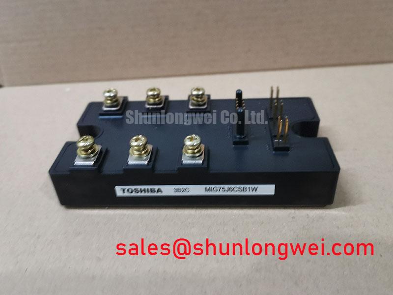
The Toshiba MIG75J6CSB1W is an Intelligent Power Module (IPM) that consolidates a complete three-phase IGBT inverter bridge and its associated gate drive and protection circuits into a single, compact package. This high level of integration provides a streamlined solution for motor control systems. Its core value lies in simplifying design, reducing component count, and enhancing system reliability through built-in protection mechanisms.
- Core Specifications: 600V | 75A | VCE(sat) (typ) = 1.8V
- Key Advantages: Integrated drive and protection circuits reduce design complexity. Low typical collector-emitter saturation voltage contributes to lower conduction losses.
- Engineering Focus: By integrating protection features, this IPM helps mitigate common failure modes such as overcurrent and short-circuits.
Download the Official MIG75J6CSB1W Datasheet (PDF)

Technical Analysis of Core Features
The MIG75J6CSB1W’s architecture is centered on providing a robust and efficient power stage for inverter applications. The integration of IGBTs with their drive circuits within a single module minimizes the parasitic inductance that often plagues designs using discrete components. Lower inductance leads to reduced voltage overshoots during high-speed switching, which can improve both EMI performance and overall system reliability. For more information on this topic, see our guide to the advantages of integrated power module structures.
A critical parameter for efficiency is the collector-emitter saturation voltage, VCE(sat), which is specified as 1.8V (typically) for this module. This value directly impacts conduction losses, especially in applications with high load currents. VCE(sat) can be thought of as the operational “cost” of having the switch turned on; a lower value means less power is dissipated as heat within the module. This efficiency allows for smaller heatsinks and potentially a more compact final product, directly addressing thermal management challenges.
The module incorporates a suite of protection features, including safeguards against short-circuit current, overcurrent, undervoltage, and overtemperature conditions. This built-in intelligence offloads critical protective functions from the main system controller. The integrated overtemperature protection, for example, is crucial for preventing thermal runaway, a common failure mechanism in power electronics. To understand this better, read our analysis on the root causes of IGBT failures.
Optimized Application Scenarios
The specific characteristics of the MIG75J6CSB1W make it highly suitable for several power conversion applications:
- AC Motor Drives & VFDs: The 6-in-1 topology is the standard configuration for three-phase motor inverters. The 75A rating is suitable for controlling motors in industrial robotics, CNC machines, and conveyor systems.
- General Purpose Inverters: The module’s robust design and integrated protection make it a reliable choice for standalone inverters and solar power applications.
- Uninterruptible Power Supplies (UPS): Its high level of integration allows for the design of power-dense UPS systems where space and reliability are key concerns.
Given its specifications, this IPM is a strong candidate for motor control systems rated up to approximately 37 kW (50 HP), assuming a 400VAC bus.
Key Specifications of the MIG75J6CSB1W
| Parameter | Symbol | Value | Conditions |
|---|---|---|---|
| Absolute Maximum Ratings (Inverter Part, Tc=25°C) | |||
| Collector-Emitter Voltage | VCES | 600 V | VGE = 0 |
| Collector Current | IC | 75 A | |
| Collector Power Dissipation | PC | 260 W | Per IGBT |
| Electrical Characteristics (Inverter Part, Tc=25°C) | |||
| Collector-Emitter Saturation Voltage | VCE(sat) | 1.8 V (typ), 2.4 V (max) | IC = 75 A |
| Forward Voltage (FWD) | VF | 1.7 V (typ), 2.3 V (max) | IC = 75 A |
| Switching Time (Turn-on) | ton | 1.2 µs (typ) | Inductive Load |
| Switching Time (Turn-off) | toff | 2.2 µs (typ) | Inductive Load |
Engineer’s FAQ
1. How does the integrated nature of the MIG75J6CSB1W affect thermal design?
The single-module design concentrates the heat source, simplifying thermal management compared to six discrete devices. An isolated metal baseplate provides a single, flat surface for mounting to a heatsink. It’s critical to use the specified mounting torque and an appropriate thermal interface material to ensure low thermal resistance and effective heat dissipation.
2. What are the key considerations for the control power supply?
The module requires a 15V supply for the control circuits. This supply should be well-regulated and placed close to the module pins. The datasheet specifies an undervoltage protection that trips if the supply drops, preventing operation with insufficient gate voltage which could damage the IGBTs.
3. How is the short-circuit protection implemented?
The MIG75J6CSB1W includes a built-in short-circuit (SC) protection function. If a fault causes the collector current to rise to a critical level, the internal protection circuit will safely shut down the corresponding IGBT and output a fault signal. This response is much faster than what can typically be achieved with external monitoring circuits.
Design Enablement
The Toshiba MIG75J6CSB1W provides engineers with a functionally dense building block for three-phase power conversion. By integrating the power stage with essential drive and protection functions, this IPM enables the development of more compact, reliable, and efficient motor control systems and inverters. Its specification set offers a balanced performance for a wide range of industrial applications.