Fuji 7MBR50UA120: Technical Analysis of an Integrated IGBT Module
Fuji 7MBR50UA120 1200V 50A 7-Pack IGBT Module
Integrated Power Stage for Compact Drive Systems
The Fuji Electric 7MBR50UA120 is a highly integrated 7-pack IGBT module that consolidates a complete power stage for compact AC drives into a single, efficient package. This module’s primary engineering advantage is its Converter-Inverter-Brake (CIB) topology, which combines a three-phase input rectifier, a brake chopper, and a three-phase output inverter. This level of integration directly addresses the need for reduced component count and simplified assembly in modern power systems.
- Core Specifications: 1200V | 50A | 7-in-1 CIB Topology
- Key Advantages: Reduces PCB footprint and assembly complexity, integrated NTC thermistor enables real-time thermal monitoring.
For detailed electrical and thermal characteristics, download the official 7MBR50UA120 datasheet (PDF).
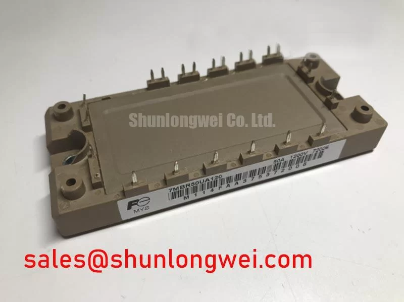

Technical Analysis of the Integrated Design
The core of the 7MBR50UA120’s utility is its functional integration. By housing seven distinct power semiconductor stages within one module, it eliminates the need for multiple discrete components and the complex interconnects they require. This not only saves valuable board space but also reduces parasitic inductance, a critical factor in managing switching performance and minimizing EMI. The single-package approach streamlines manufacturing and can improve the overall reliability of the final system by reducing the number of solder joints and potential points of failure. This module is an example of a Power Integrated Module (PIM), offering a strategic advantage over discrete designs.
Thermal Management and System Reliability
Effective thermal management is fundamental to the reliability of any power module. The 7MBR50UA120 datasheet specifies a thermal resistance from junction to case (Rth(j-c)) of 0.50°C/W for each inverter IGBT. This value can be thought of like the width of a pipe for heat dissipation; a lower value indicates a wider pipe, allowing heat to escape more efficiently from the semiconductor junction to the heatsink. Furthermore, the inclusion of an integrated NTC thermistor provides a direct method for monitoring the module’s internal temperature. This allows the system controller to implement precise over-temperature protection or to dynamically adjust performance, safeguarding the IGBT from thermal runaway conditions.

Optimized Application Scenarios
The specific characteristics of the 7MBR50UA120 make it a strong candidate for several applications:
- Compact Motor Drives: The all-in-one CIB configuration is ideal for small Variable Frequency Drives (VFDs) where space is at a premium.
- Servo Drives: Its 50A current rating and integrated brake chopper provide the necessary control for AC servo systems requiring dynamic braking and precise positioning.
- General-Purpose Inverters: For industrial power conversion tasks, this module offers a complete, pre-engineered power stage that can accelerate development time.
- Uninterruptible Power Supplies (UPS): The converter and inverter sections are well-suited for the AC-DC and DC-AC stages found in online UPS systems.
Its integrated topology is an optimal match for space-constrained applications requiring a complete AC motor drive power stage, typically up to 22kW.
Key Specification Parameters
| Absolute Maximum Ratings (Tc=25°C unless otherwise specified) | |
|---|---|
| Collector-Emitter Voltage (Vces) | 1200 V |
| Continuous Collector Current (Ic) | 50 A (Tc=80°C) |
| Total Power Dissipation (Pc) | 300 W |
| Operating Junction Temperature (Tj) | +150 °C |
| Electrical Characteristics (Inverter Part) | |
| Collector-Emitter Saturation Voltage (VCE(sat)) | 2.2 V (typ) / 2.7 V (max) at Ic = 50A |
| FWD Forward Voltage (Vf) | 2.0 V (typ) / 2.5 V (max) at If = 50A |
| Thermal Characteristics | |
| Thermal Resistance, Junction-to-Case (Rth(j-c)) – Inverter IGBT | 0.50 °C/W |
| Thermal Resistance, Junction-to-Case (Rth(j-c)) – Inverter FWD | 0.83 °C/W |
Engineer FAQ
- How can I use the thermal resistance value for heatsink selection?
- To estimate the required heatsink thermal resistance (Rth(f-a)), you first calculate the total power loss (Ploss) of the module under your operating conditions. Then, use the formula: Rth(f-a) ≤ (Tj_max – Ta) / Ploss – Rth(j-c) – Rth(c-f). Where Ta is ambient temperature and Rth(c-f) is the thermal resistance of the interface material. The datasheet provides graphs to help calculate losses.
- What is the function of the integrated NTC thermistor?
- The built-in NTC thermistor provides a means for real-time temperature feedback from the module’s baseplate. It has a nominal resistance of 5 kΩ at 25°C and a B-constant of 3375K. This data can be used by the system’s microcontroller to trigger alarms, reduce output power, or initiate a shutdown if the temperature exceeds safe limits.
- What are the recommended gate drive voltage conditions for the 7MBR50UA120?
- The datasheet specifies the gate-emitter threshold voltage VGE(th) between 5.0V and 7.5V. For reliable operation, a positive turn-on voltage of +15V is recommended for the gate drive. For turn-off, a negative gate voltage between -5V and -15V is advised to ensure noise immunity and prevent spurious turn-on.
- Is it necessary to use the brake chopper circuit?
- No. If your application, such as a fan or pump controller, does not require dynamic braking to dissipate regenerative energy, the brake chopper terminals (P-B and B-N1) can be left unconnected without affecting the operation of the inverter or converter sections.
Enabling Power Density and System Simplicity
This module provides a streamlined path for developing reliable and compact power conversion systems. The integrated CIB topology within the 7MBR50UA120 minimizes external circuitry and simplifies thermal design, directly supporting engineering goals for higher power density and faster time-to-market in modern industrial drives.