CM400DY-12NF: A Technical Review of a High-Current Dual IGBT Module
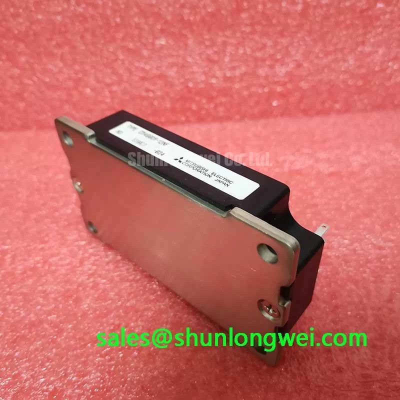
CM400DY-12NF Mitsubishi 600V 400A Dual IGBT Module
Introduction and Core Highlights
The Mitsubishi CM400DY-12NF is a high-current dual IGBT module delivering robust power switching for demanding industrial applications. This module is engineered for reliability, providing a stable and efficient solution for high-power inverters, servo drives, and power supplies. It achieves a proficient balance between conduction losses and switching performance, underscored by its proven short-circuit ruggedness, making it a dependable component for system designers.
- Core Specifications: 600V | 400A | VCE(sat) 2.2V (typ.)
- Key Advantages: High current density in a standard package, proven system reliability with a 10µs short-circuit withstand time.
This module’s thermal characteristics are well-defined, allowing engineers to accurately model and implement effective thermal management strategies for long-term operational stability.
Download the Official CM400DY-12NF Datasheet (PDF)

Technical Analysis for System Integration
The CM400DY-12NF is built around a balance of performance and durability. A key parameter is its collector-emitter saturation voltage (VCE(sat)), with a typical value of 2.2V at its nominal 400A current rating. This specification is a direct indicator of conduction losses—the primary source of heat generation during the on-state. A lower VCE(sat) translates to less power dissipated as heat, which simplifies cooling system requirements and improves overall energy efficiency. This is particularly vital in applications with high duty cycles where the IGBT spends a significant amount of time conducting current.
System reliability is heavily influenced by the module’s ability to withstand fault conditions. The datasheet specifies a short-circuit withstand time (tsc) of 10µs (minimum). This rating defines the duration for which the IGBT can survive a direct short-circuit across its terminals before catastrophic failure. This 10µs window provides critical time for the system’s protection circuitry to detect the fault and safely shut down the gate drive. Think of it as the device’s built-in safety margin; a longer withstand time allows for more robust and less sensitive protection schemes, preventing nuisance tripping while ensuring the protection of the power stage in efficient power conversion systems.

Optimized Application Scenarios
The specifications of the CM400DY-12NF make it a strong candidate for several high-power industrial applications:
- AC Motor Controls & VFDs: Its 400A current capability is well-suited for driving medium-to-large three-phase induction motors. The module’s thermal efficiency is critical for maintaining performance in enclosed drive cabinets.
- Uninterruptible Power Supplies (UPS): The high reliability and proven ruggedness, including its short-circuit rating, are essential for backup power systems where uptime is non-negotiable.
- Welding Power Supplies: Welders demand components that can handle high-current pulses. This module’s ability to manage a peak collector current of 800A makes it suitable for such demanding, repetitive load conditions.
- General Purpose Inverters: The half-bridge configuration is a fundamental building block for DC-AC power conversion, and this module provides a high-power, integrated solution.
This module is an optimal choice for industrial power systems requiring a durable, high-current switch with straightforward gate drive design.
Key Specifications of the CM400DY-12NF
| Absolute Maximum Ratings | ||
|---|---|---|
| Collector-Emitter Voltage (VCES) | 600V | |
| Collector Current (DC) (IC) | 400A | |
| Peak Collector Current (ICP) | 800A | |
| Maximum Power Dissipation (PC) | 1130W | |
| Operating Junction Temperature (Tj) | -40 to +150°C | |
| Electrical & Thermal Characteristics | ||
| Collector-Emitter Saturation Voltage (VCE(sat)) | 2.2V (typ) / 2.7V (max) @ IC=400A | |
| Gate-Emitter Threshold Voltage (VGE(th)) | 4.5V to 8.5V | |
| FWDi Forward Voltage (VEC) | 2.1V (typ) / 2.6V (max) @ IE=400A | |
| Thermal Resistance (Rth(j-c)Q, IGBT) | 0.085°C/W | |
| Isolation Voltage (Visol) | 2500 Vrms | |
Engineer’s FAQ
- How does the VCE(sat) of the CM400DY-12NF impact system efficiency?
- The VCE(sat) directly determines conduction loss (Pcond ≈ VCE(sat) × IC × Duty Cycle). With a typical VCE(sat) of 2.2V at 400A, the module is optimized to balance on-state losses with switching performance, contributing to good overall efficiency in applications operating at low-to-moderate frequencies (e.g., up to ~15 kHz).
- What are the key considerations for mounting and heatsink selection for this module?
- Proper mounting is crucial for effective heat dissipation. Ensure a flat (within 50µm) and clean heatsink surface. Use a high-quality thermal compound and apply the recommended mounting torque of 3.5 – 4.5 N·m to the M6 mounting screws to achieve the specified thermal resistance (Rth(c-f)) of 0.03 °C/W. The heatsink must be sized to keep the case temperature (Tc) below the limits dictated by the maximum junction temperature of 150°C under worst-case load conditions.
- What is the purpose of the freewheeling diode (FWD) in this dual module?
- The FWD is a super-fast recovery diode connected in anti-parallel with each IGBT. In inductive load applications like motor drives, it provides a path for the current to flow when the IGBT is turned off, protecting the IGBT from potentially damaging overvoltage spikes. Its soft recovery characteristics are designed to minimize EMI.
Design Enablement
By providing a robust foundation of high current capacity, a well-balanced loss profile, and dependable short-circuit protection, the CM400DY-12NF enables engineers to design efficient and resilient power conversion systems. Its standard industrial package ensures straightforward integration and scalability for a wide range of applications.