Fuji 2MBI150VH-170-50: V-Series IGBT for Efficient High-Voltage Applications
Fuji 2MBI150VH-170-50 IGBT Module | 1700V 150A
High-Voltage Performance with V-Series Technology
The Fuji Electric 2MBI150VH-170-50 is a 1700V dual IGBT module engineered to provide a superior balance of low power loss and high-speed, reliable operation for demanding power conversion systems. This module leverages Fuji’s advanced V-Series technology, which incorporates a trench gate and field-stop structure to optimize switching characteristics and reduce thermal load. The result is a component that enhances overall system efficiency.
- Core Specifications: 1700V | 150A | VCE(sat) (typ) 2.2V
- Key Advantages: Minimized conduction and switching losses, excellent thermal dissipation.
By achieving a low collector-emitter saturation voltage, this module directly addresses the need for reduced heat generation, simplifying thermal management requirements in high-power designs.
Download Official Datasheet (PDF)
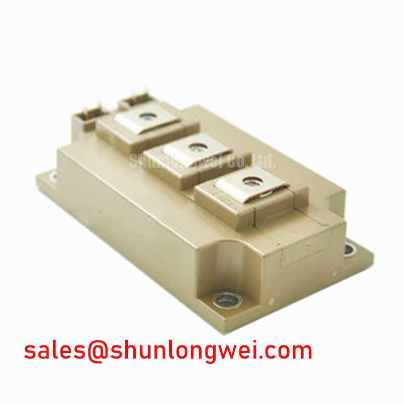


Technical Analysis of V-Series Performance
The engineering value of the 2MBI150VH-170-50 is rooted in its V-Series chip technology. This design achieves a low typical VCE(sat) of 2.2V at its nominal 150A current, which directly curtails conduction losses. This parameter is a critical factor in overall system efficiency, particularly in applications with high duty cycles. A lower VCE(sat) means less power is dissipated as heat while the device is active, allowing for smaller heatsinks and potentially higher power density in the final product.
Furthermore, the module’s thermal design facilitates long-term reliability. Its specified thermal resistance from junction to case (Rth(j-c)) for the IGBT is 0.08 K/W per arm. This value can be thought of like the width of a pipe for heat; a lower number signifies a wider pipe, allowing heat to escape the semiconductor junction more easily. This efficient heat transfer is crucial for preventing the device from exceeding its maximum operating junction temperature of 175°C, ensuring stable performance under demanding load conditions. More details on such topics can be found in our guide to mastering IGBT thermal design.
Optimized Application Scenarios
The specific characteristics of the 2MBI150VH-170-50 make it a strong candidate for several high-voltage applications:
- Solar Inverters: The 1700V collector-emitter voltage provides a substantial safety margin for 1000V DC bus systems, and its low-loss operation helps maximize energy conversion efficiency.
- Uninterruptible Power Supplies (UPS): High efficiency and robust thermal performance are critical for UPS reliability. This module’s design helps reduce cooling requirements and improve the longevity of the system.
- Industrial Motor Drives: The module’s capacity to handle 150A continuous current and its fast, controlled switching make it well-suited for AC and DC servo drives and general-purpose inverters.
- Welding Machines: The robust Safe Operating Area (SOA) and high current handling are beneficial for the pulsed-power conditions found in industrial welding equipment.
This module is best matched for high-voltage power systems where achieving a balance between high efficiency and long-term operational reliability is a primary design objective.
Key Specifications of the 2MBI150VH-170-50
| Absolute Maximum Ratings (Tc = 25°C unless otherwise specified) | ||
|---|---|---|
| Collector-Emitter Voltage (Vces) | 1700V | |
| Gate-Emitter Voltage (Vges) | ±20V | |
| Continuous Collector Current (Ic) | 150A (Tc=80°C) | |
| Max. Junction Temperature (Tjmax) | 175°C | |
| Electrical Characteristics (Tj = 25°C) | ||
| Collector-Emitter Saturation Voltage (VCE(sat)) | 2.2V (typ) at Ic = 150A, Vge = 15V | |
| Gate-Emitter Threshold Voltage (VGE(th)) | 6.0V to 7.0V | |
| FWD Forward Voltage (VF) | 2.15V (typ) at IF = 150A | |
Engineer’s FAQ
1. What are the primary thermal management considerations for the 2MBI150VH-170-50?
The key is to ensure the junction temperature remains below the 150°C (operating) / 175°C (max) limits. Given the Rth(j-c) of 0.08 K/W for the IGBT, a heatsink with sufficiently low thermal resistance must be selected. Proper mounting with a recommended torque of 3.0-6.0 N·m and the use of thermal grease are critical for effective heat transfer.
2. What is the recommended gate drive voltage?
The datasheet specifies electrical characteristics based on a gate-emitter voltage (Vge) of ±15V. Operating within this range is recommended to achieve the specified VCE(sat) and switching performance. A negative gate voltage is often advised to prevent spurious turn-on, a topic explored in our article on enhancing IGBT noise immunity.
3. Can these IGBT modules be connected in parallel?
Yes, but careful design is required. To ensure proper current sharing, designers must ensure symmetrical PCB layouts to balance stray inductances and use gate drivers with a separate gate resistor for each module. The positive temperature coefficient of VCE(sat) in V-Series IGBTs aids in balancing current under static conditions.
4. How does the V-Series technology impact performance compared to older generations?
V-Series technology uses a thinner wafer with a trench gate and field-stop (FS) structure. This combination significantly reduces both on-state voltage (VCE(sat)) and switching losses compared to earlier planar or non-punch-through (NPT) designs. This leads to higher inverter efficiency and reduced heat generation. For more information, read about the evolution of trench gate technology.
Enabling Efficient High-Voltage Systems
The 2MBI150VH-170-50 delivers a well-defined set of performance characteristics for engineers developing high-voltage power electronics. Its foundation in Fuji’s proven V-Series technology provides a direct path to achieving lower power losses and robust thermal stability, enabling the creation of more compact, efficient, and reliable power conversion systems.