Fuji 2MBI400N-060 (600V/400A) IGBT Module: A Technical Review
Fuji 2MBI400N-060 N-Series IGBT Module | 600V 400A
Introduction and Core Highlights
The Fuji Electric 2MBI400N-060 is a high-current N-Series IGBT module that delivers a robust solution for high-power switching applications. Its primary value lies in its substantial current handling capability combined with proven reliability in an industry-standard package. This enables the design of power-dense and dependable systems. The total power dissipation is a critical parameter for thermal design, and for this module, it is specified at 1300W, a figure that directly informs heatsink selection and cooling strategies. This module provides a solid foundation for systems requiring precise control over significant electrical loads.
- Core Specifications: 600V | 400A | VCE(sat) 2.7V (max)
- Key Advantages: Exceptional current handling for power-dense designs, established reliability of the N-Series.
Download the Official 2MBI400N-060 Datasheet (PDF)

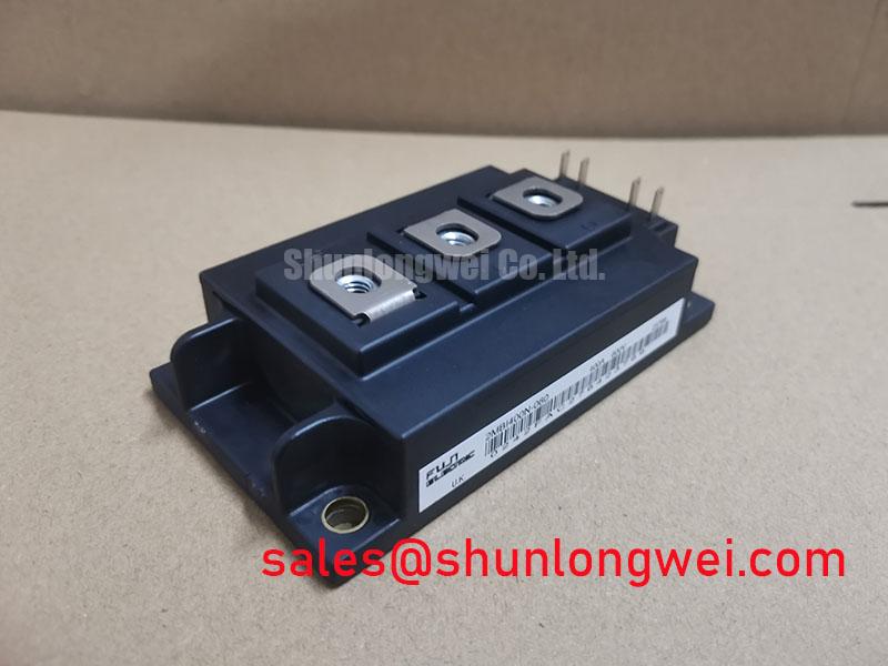
Technical Analysis of Core Features
The standout characteristic of the 2MBI400N-060 is its continuous DC collector current (Ic) rating of 400A (at a case temperature of 25°C). This high current capacity is fundamental for applications like large motor drives, where substantial current is required to generate the necessary torque. The module’s dual configuration (two IGBTs in one package) simplifies the construction of half-bridge topologies, which are the building blocks for three-phase inverters. This integration reduces component count and simplifies the busbar layout compared to using discrete devices, contributing to a more compact and reliable system.
Another critical parameter for power system design is the collector-emitter saturation voltage, VCE(sat). For the 2MBI400N-060, the maximum VCE(sat) is specified as 2.7V at the nominal 400A current. This voltage represents the power lost as heat during the on-state of the switch. You can think of thermal resistance (Rth) as the width of a pipe for heat; a lower value means heat can escape more easily. The module’s junction-to-case thermal resistance of 0.096°C/W per IGBT provides a clear path for calculating heat dissipation, ensuring the device operates below its maximum junction temperature of 150°C.
Optimized Application Scenarios
The specifications of this module make it a strong candidate for several high-power industrial applications:
- AC Motor Drives: The 400A current rating is well-suited for controlling the speed and torque of large industrial motors.
- High-Power Inverters: Its 600V VCES and dual configuration are ideal for constructing inverter phases in systems like large-scale uninterruptible power supplies (UPS).
- Welding Power Supplies: The module’s robust thermal characteristics and high current capability can withstand the demanding, cyclical loads found in industrial welding equipment.
- Switch Mode Power Supplies (SMPS): In high-power SMPS, this module can serve as the primary switching element, offering reliable performance.
This module is an optimal match for high-power systems requiring proven reliability and straightforward thermal management in the sub-5kHz switching frequency range.
Key Specification Parameters
| Absolute Maximum Ratings (at Tc=25°C unless otherwise specified) | |
|---|---|
| Collector-Emitter Voltage (VCES) | 600V |
| Gate-Emitter Voltage (VGES) | ±20V |
| Continuous Collector Current (IC) | 400A |
| 1ms Repetitive Peak Collector Current (IC(pulse)) | 800A |
| Max Power Dissipation (Pc) | 1300W (per IGBT) |
| Operating Junction Temperature (Tj) | +150°C |
| Electrical Characteristics | |
| Collector-Emitter Saturation Voltage (VCE(sat)) (Max) | 2.7V (at Ic=400A, VGE=15V) |
| Thermal Resistance, Junction to Case (Rth(j-c)) (IGBT) | 0.096°C/W |
| Thermal Resistance, Junction to Case (Rth(j-c)) (Diode) | 0.16°C/W |
Engineer’s FAQ
1. What are the primary factors for calculating power loss in the 2MBI400N-060?
Total power loss is the sum of conduction loss and switching loss. Conduction loss is calculated using VCE(sat) and the load current. Switching loss is determined by the turn-on (Eon) and turn-off (Eoff) energies, which depend on collector current and bus voltage, multiplied by the switching frequency. Both VCE(sat) curves and switching energy charts are available in the official datasheet.
2. What is the recommended mounting torque for this module?
The datasheet specifies a mounting torque for the main terminals (M8) of 8-10 Nm and for the mounting screws (M6) of 3-5 Nm. Applying the correct torque is critical for minimizing thermal resistance and ensuring mechanical stability.
3. What is the maximum permissible case temperature (Tc)?
While the maximum junction temperature (Tj) is 150°C, the allowable case temperature depends on the power being dissipated. You must calculate the temperature rise from the case to the junction using the thermal resistance (Rth(j-c)) to ensure Tj max is not exceeded under worst-case operating conditions.
4. Does the 2MBI400N-060 contain one or two IGBTs?
This is a dual or “2-in-1” module. It contains two NPT IGBT transistors along with two corresponding free-wheeling diodes, typically arranged in a half-bridge configuration.
Design and Application Notes
The Fuji 2MBI400N-060 provides a well-documented and robust platform for high-power control systems. Its high current rating simplifies the power stage, while its standard package facilitates straightforward mechanical and thermal integration. For engineers designing systems where reliability and power throughput are paramount, this module offers a proven and effective solution. Understanding the interplay between IGBT failures and thermal design is key to maximizing system lifespan.