Fuji 2MBI400TB-060 Dual IGBT Module: Technical Specifications and Applications
Fuji 2MBI400TB-060 Dual IGBT Module: 600V 400A Specs
Product Overview & Core Technical Highlights
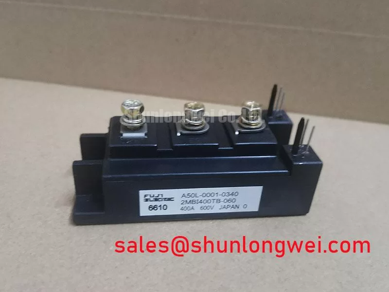
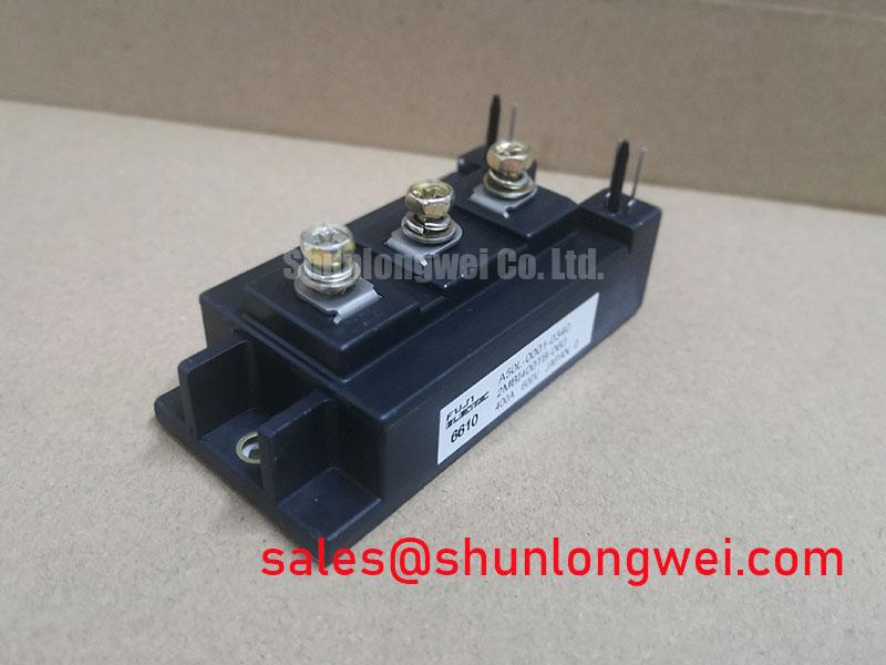
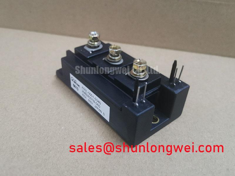
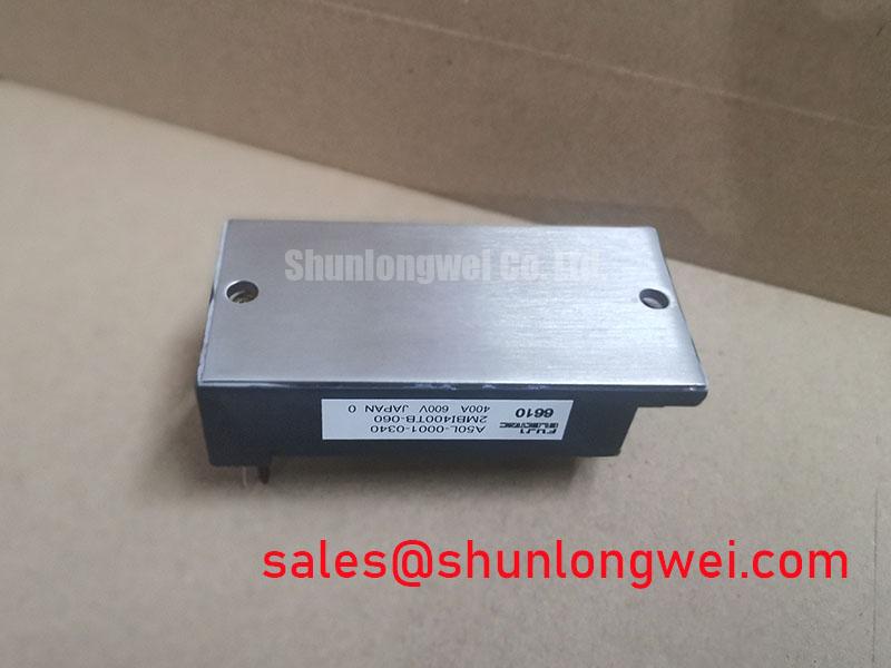
The Fuji 2MBI400TB-060 is a 600V, 400A dual IGBT module engineered in a half-bridge topology for high-current power conversion. Designed to deliver low conduction loss and balanced thermal performance, this module simplifies inverter assembly while maintaining high electrical efficiency.
- Core Specifications: 600V collector-emitter voltage ($V_{CES}$), 400A continuous collector current ($I_C$), and 2500V AC electrical isolation.
- Engineering Advantages: Low thermal impedance reduces heatsink volume requirements, while optimized diode recovery characteristics minimize electromagnetic interference.
Engineers designing high-power motor drives or battery power supplies can verify exact switching limits and mechanical tolerances directly from the official documentation.
Download Official 2MBI400TB-060 Datasheet (PDF)

Technical Analysis & Performance Characteristics
The 2MBI400TB-060 utilizes high-speed silicon die technology optimized for medium-voltage, high-amperage switching. At a nominal collector current of 400A, the module maintains a low collector-emitter saturation voltage ($V_{CE(sat)}$). This directly minimizes conduction losses during continuous operation, reducing cooling system demands in enclosed cabinets.
Thermal management in high-current switching modules depends heavily on junction-to-case thermal resistance ($R_{th(j-c)}$). Think of thermal resistance like a bottleneck in a water pipe; a smaller value allows heat generated at the silicon junction to flow rapidly into the heatsink. By minimizing this thermal barrier, the module prevents junction overheating and mitigates failure mechanisms discussed in our root cause analysis of IGBT failures.
Each switch position integrates a fast-recovery freewheeling diode (FWD) with soft-recovery dynamics. This configuration limits reverse recovery current spikes ($I_{rr}$) and dampens voltage ringing during high $di/dt$ transitions. When combined with appropriate gate resistor selection, the module delivers dependable performance within modern power semiconductors assemblies.
Optimized Application Scenarios
- Industrial AC Motor Drives: The 600V rating matches 200V–240V AC line rectified buses, handling variable frequency drive inverter stages efficiently.
- Uninterruptible Power Supplies (UPS): Fast switching capability and low conduction loss support high-efficiency sine-wave inverter outputs under varying load conditions.
- Industrial Welding Inverters: A high pulsed collector current rating ($I_{CP} = 800A$) accommodates rapid load changes without triggering desaturation faults.
- High-Current DC-DC Converters: The half-bridge layout simplifies symmetrical layout routing when implementing a low-inductance busbar design.
The module provides a reliable, thermally optimized switching foundation for 200V-line high-current industrial motor drives and power conversion systems.
Key Specifications Parameter Table
| Parameter Category | Symbol | Datasheet Rating / Value | Unit |
|---|---|---|---|
| Collector-Emitter Voltage | $V_{CES}$ | 600 | V |
| Continuous Collector Current | $I_C$ | 400 | A |
| Pulsed Collector Current (1ms) | $I_{CP}$ | 800 | A |
| Gate-Emitter Voltage | $V_{GES}$ | ±20 | V |
| Collector-Emitter Saturation Voltage | $V_{CE(sat)}$ (typ.) | 2.30 (at $I_C=400A, V_{GE}=15V$) | V |
| Isolation Voltage (AC 1 min) | $V_{isol}$ | 2500 | V |
| Thermal Resistance (IGBT per device) | $R_{th(j-c)}$ | 0.085 | °C/W |
Engineer FAQs
How should gate resistance ($R_G$) be selected for 600V high-current inverters?
Gate resistance balances switching speed and turn-off voltage overshoot. A lower $R_G$ accelerates switching and reduces switching loss ($E_{on}/E_{off}$), but increases $dv/dt$ and transient voltage spikes. Engineers should review the datasheet switching loss curves and use snubber circuits to ensure the voltage remains below 600V $V_{CES}$.
What are the recommended mounting guidelines to ensure proper heat dissipation?
The mounting surface must be clean and flat (roughness $le 10,mutext{m}$, flatness $le 50,mutext{m}$). Apply a uniform layer of thermal grease (60–100 $mutext{m}$ thickness) across the baseplate. Tighten mounting screws in sequence to the specified torque rating (typically 3.5 to 4.5 N·m) to prevent baseplate deformation.
Does the module include internal protection circuits or a thermistor?
No. The 2MBI400TB-060 is a standard dual IGBT module containing two switches and two antiparallel diodes. External gate driver circuitry must provide desaturation detection, active clamping, and temperature monitoring.
Design Integration Overview
Implementing the 2MBI400TB-060 provides a proven power stage solution for 600V-class industrial applications. Its balanced saturation voltage, robust diode recovery characteristics, and low thermal resistance enable engineers to build compact, efficient power conversion equipment.