Fuji 7MBI75SA-120B-50 Review: An Integrated 1200V IGBT for Efficient Motor Drives
Fuji 7MBI75SA-120B-50 IGBT Module | 1200V 75A 7-in-1 PIM
Introduction and Core Highlights
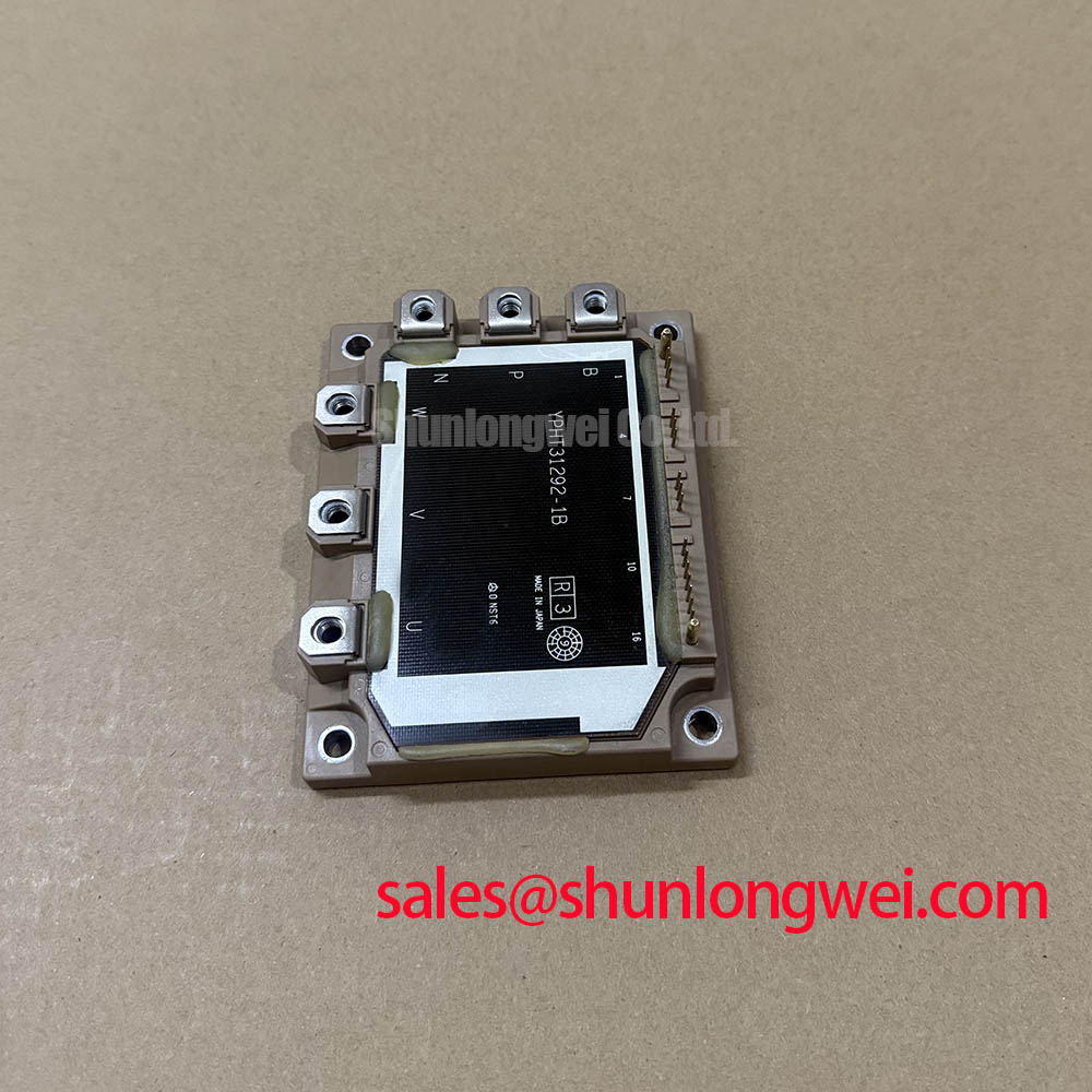
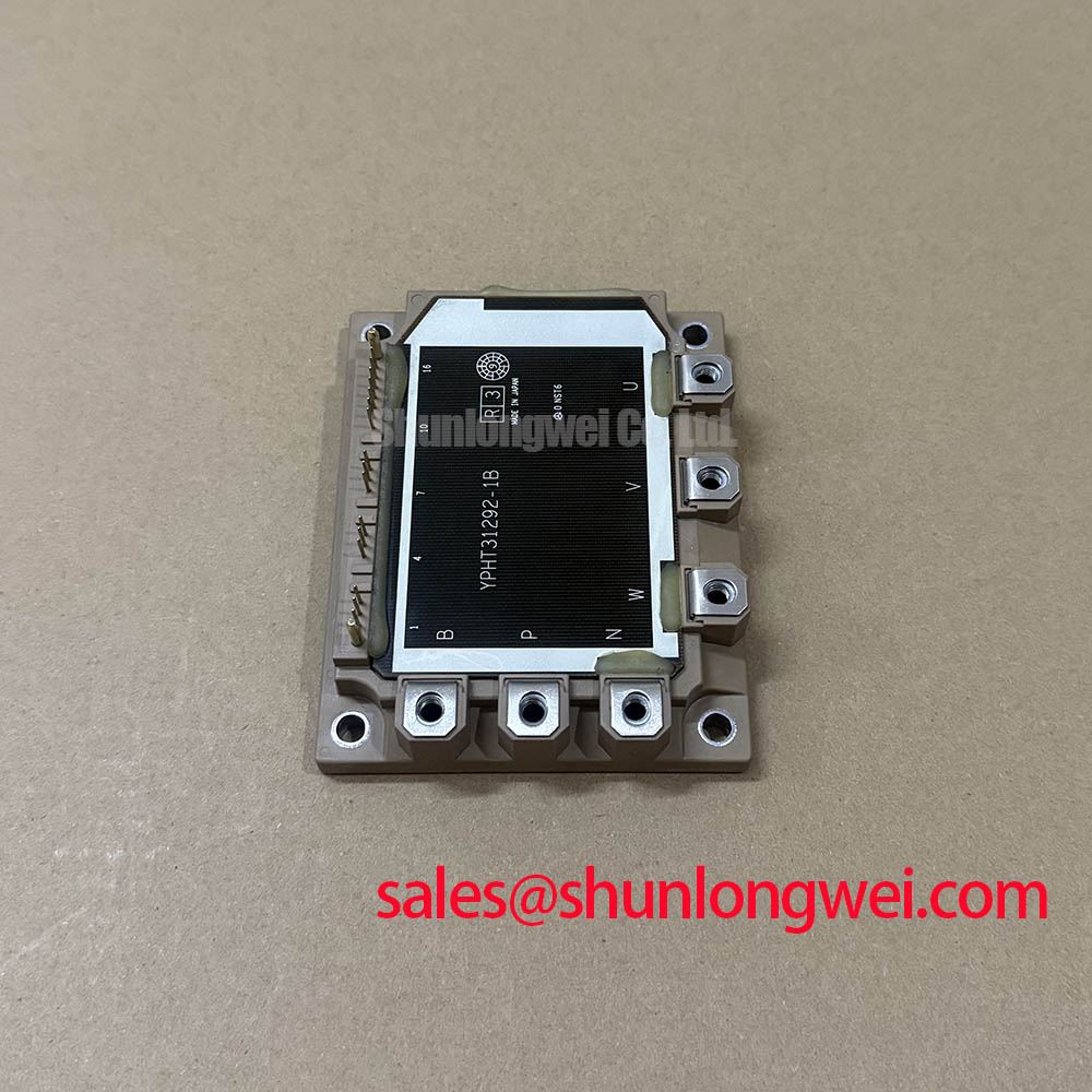
The Fuji Electric 7MBI75SA-120B-50 is a highly integrated V-Series IGBT module that combines a three-phase inverter and a brake chopper into a single compact package. This module’s primary engineering value is its ability to reduce system complexity and improve thermal efficiency through its low-loss characteristics. It provides a robust foundation for building reliable and efficient motor control systems.
- Core Specifications: 1200V | 75A | VCE(sat) 1.70V (typ.)
- Key Advantages: Reduces system component count and simplifies PCB layout. The integrated NTC thermistor enables precise thermal monitoring for enhanced reliability.
- User Intent Answered: For engineers developing compact variable frequency drives (VFDs), the 7-in-1 configuration of the 7MBI75SA-120B-50 streamlines the power stage design by integrating seven IGBTs and their corresponding freewheeling diodes.
Download the Official Datasheet (PDF)


Technical Analysis Based on the UVP
The engineering advantage of the 7MBI75SA-120B-50 is rooted in its intelligent integration and focus on efficiency. The 7-in-1 topology consolidates the complete power stage for a motor drive—including the brake circuit—into one component. This significantly reduces the parasitic inductance that can occur in designs using discrete components, leading to cleaner switching waveforms and potentially lower EMI. Furthermore, it simplifies procurement and assembly, which are critical factors in scalable production environments.
A key performance indicator is the low collector-emitter saturation voltage (VCE(sat)), specified with a typical value of 1.70V at a junction temperature of 125°C. This parameter can be thought of like a valve’s resistance to flow; a lower VCE(sat) indicates less voltage drop across the IGBT when it is fully on. This directly translates to lower conduction losses, meaning less energy is wasted as heat. For the system designer, this allows for the use of smaller, more cost-effective heatsinks and improves the overall energy efficiency of the end application.
Reliability is further enhanced by the inclusion of an NTC thermistor. This component provides a real-time temperature reading directly from the module’s substrate. This data is essential for implementing over-temperature protection in the system’s control logic. Accurate thermal feedback prevents the module from operating beyond its safe thermal limits, a critical aspect for ensuring long operational life in demanding industrial environments. Understanding this feature is key to leveraging the module’s full potential for IGBT module safety and reliability.
Optimized Application Scenarios
The specific characteristics of the 7MBI75SA-120B-50 make it a strong candidate for several applications:
- Variable Frequency Drives (VFDs): The 7-in-1 configuration provides the exact topology needed for a three-phase motor inverter with dynamic braking capabilities, simplifying the VFD’s power stage.
- AC Servo Drives: Its low conduction losses contribute to the high efficiency required in precision motion control, while the compact package suits space-constrained servo systems.
- General Purpose Inverters: The 1200V blocking voltage and 75A current rating offer a robust solution for a wide range of industrial power conversion tasks.
- Uninterruptible Power Supplies (UPS): High reliability and integrated thermal sensing are critical for UPS systems where continuous operation is non-negotiable.
This module is an optimal power stage for motor control systems up to approximately 30 kW requiring high integration, reliability, and thermal efficiency.
Key Specification Parameters
| Absolute Maximum Ratings (Tc=25°C unless otherwise specified) | |||
|---|---|---|---|
| Parameter | Symbol | Value | |
| Collector-Emitter Voltage | VCES | 1200V | |
| Gate-Emitter Voltage | VGES | ±20V | |
| Inverter Continuous Collector Current (Tc=80°C) | IC | 75A | |
| Collector Power Dissipation (1 device) | PC | 440W | |
| Operating Junction Temperature | Tj | +150°C | |
| Electrical Characteristics (Tj=25°C unless otherwise specified) | |||
| Parameter | Symbol | Test Condition | Typ. / Max. Value |
| Collector-Emitter Saturation Voltage (Inverter) | VCE(sat) | IC=75A, VGE=15V, Tj=125°C | 1.70V / 2.15V |
| Forward Voltage (FWD) | VF | IF=75A, VGE=0V, Tj=125°C | 1.75V / 2.20V |
| Turn-on Switching Loss (Inverter) | Eon | VCC=600V, IC=75A, Tj=125°C | 13.0 mJ/pulse (typ.) |
| Turn-off Switching Loss (Inverter) | Eoff | 13.5 mJ/pulse (typ.) | |
| Thermal Resistance (Junction to Case, IGBT) | Rth(j-c) | Per IGBT | 0.284 K/W (max) |
Engineer’s FAQ
- What is the primary benefit of the 7-in-1 configuration in the 7MBI75SA-120B-50 for a motor drive?
- The main benefit is system simplification. It integrates the three-phase inverter and the brake chopper into a single module. This reduces the number of high-power components, simplifies the busbar and PCB design, minimizes assembly labor, and lowers stray inductance compared to a solution built with discrete modules.
- How should the integrated NTC thermistor be used for effective thermal protection?
- The NTC thermistor provides a resistance that changes predictably with the module’s base plate temperature. The datasheet provides the R-T curve (Resistance-Temperature characteristic). An external circuit should monitor this resistance and the control system’s firmware should be programmed to trigger an alarm or a shutdown sequence if the calculated temperature exceeds the safe operating limits, typically set below the maximum junction temperature of 150°C.
- The datasheet specifies VCE(sat) at Tj=25°C and Tj=125°C. Which value is more relevant?
- The value at Tj=125°C is far more relevant for real-world applications. Under load, an IGBT’s junction temperature will rise significantly. The 125°C specification provides a more accurate representation of the conduction losses you can expect during normal operation, which is essential for accurate thermal design and efficiency calculations.
- What is the recommended mounting torque for the module terminals?
- According to the datasheet, the recommended mounting screw torque is 2.5 to 3.5 N·m. Adhering to this specification is crucial. Insufficient torque can lead to high contact resistance and localized overheating, while excessive torque can damage the module’s internal structure and compromise its isolation barrier, leading to catastrophic failure. A calibrated torque wrench is essential for installation.
Enabling Efficient and Reliable Power Conversion
The 7MBI75SA-120B-50 provides system designers with a highly integrated and thermally efficient foundation. Its combination of low conduction losses and a comprehensive 7-in-1 topology streamlines the development of reliable and compact power conversion systems. This allows engineering teams to focus on system-level performance while relying on a proven power stage solution from a leading manufacturer like Fuji Electric.