Fuji 7MBP150KB060 IPM: Technical Analysis and Application Guide
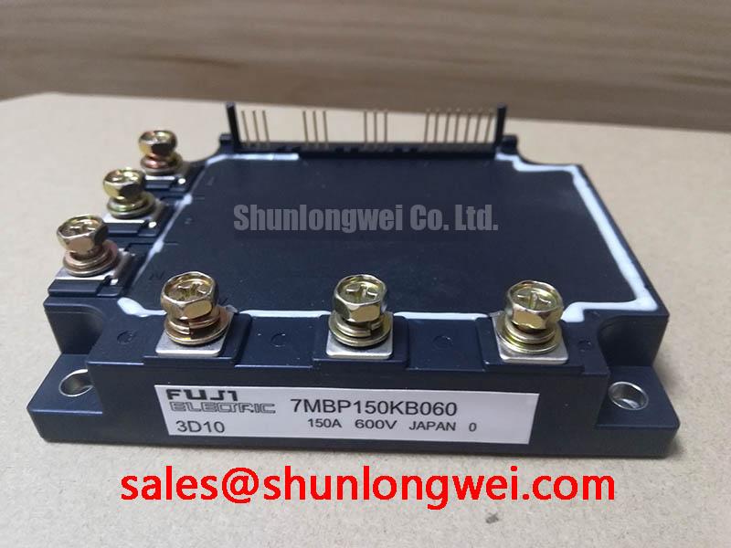
Fuji 7MBP150KB060 | 600V 150A PIM IGBT Module
Integrated 7-in-1 Power Module for Motor Drive Applications
The Fuji Electric 7MBP150KB060 is an Intelligent Power Module (IPM) that integrates a full three-phase IGBT inverter, a brake chopper, and their associated gate drive and protection circuits into a single, compact package. This high level of integration is engineered to streamline the design of AC motor drives and other power conversion systems by minimizing component count and simplifying PCB layout. It offers a robust solution for controlling three-phase motors with built-in safeguards.
- Core Specifications: 600V | 150A | 7-in-1 PIM Configuration.
- Key Advantages: Includes built-in over-current, short-circuit, under-voltage, and over-temperature protection. Reduces system complexity and enhances operational reliability.
- Design Simplification: Eliminates the need for separate gate drivers and complex protection logic, accelerating development cycles for power system design.
Download Official Datasheet (PDF)

Technical Analysis of the 7MBP150KB060
The primary value of the 7MBP150KB060 lies in its functional integration. By housing seven IGBTs (a six-pack inverter and a one-pack brake) along with dedicated low-voltage ICs for driving and protection, the module effectively creates a self-contained power stage. This architecture significantly reduces the parasitic inductance that often plagues designs using discrete components. Lower inductance leads to cleaner switching waveforms and reduced voltage overshoots, contributing to both improved EMI performance and overall system reliability.
A critical parameter for any power module is its ability to dissipate heat. The datasheet specifies the thermal resistance from junction to case (Rth(j-c)) for both the inverter and brake IGBTs. Think of thermal resistance like the width of a pipe; a lower value signifies a wider pipe, allowing heat to flow away from the silicon chip more easily. The module’s specified thermal resistance ensures that heat generated during high-current operation can be efficiently transferred to an external heatsink, a vital factor for maintaining the device within its safe operating temperature and ensuring long-term operational stability.
The integrated protection features provide a safety net against common failure modes. The module includes circuits for over-current (OC), short-circuit (SC), under-voltage (UV) lockout, and over-temperature (OT) detection. Upon detecting a fault, the module’s control IC shuts down the IGBTs in a controlled manner and outputs an alarm signal. This autonomous protection prevents catastrophic device failure and simplifies the design of the system’s external control and safety logic.
Optimized Application Scenarios
The characteristics of the 7MBP150KB060 make it an excellent component choice for several specific power applications:
- AC Motor Drives: The 7-in-1 topology is a direct fit for variable frequency drives (VFDs) that require dynamic braking to decelerate high-inertia loads. The integrated brake chopper simplifies this requirement.
- Servo Amplifiers: High-performance servo systems benefit from the module’s integrated protection and compact footprint, enabling precise motion control with a high degree of reliability.
- Industrial Robotics: The module’s robust design and comprehensive fault detection are well-suited for the demanding, repetitive load cycles found in robotic arm controllers.
- General-Purpose Inverters: Its 150A current rating and 600V breakdown voltage are suitable for a wide range of industrial power conversion tasks.
This module is best matched for systems requiring a compact, reliable, and pre-validated power stage for three-phase loads up to approximately 15-22 kW.
Key Specifications of the 7MBP150KB060
| Absolute Maximum Ratings (Tc = 25°C) | |||
|---|---|---|---|
| Symbol | Parameter | Section | Value |
| VCES | Collector-Emitter Voltage | Inverter/Brake | 600V |
| ±IC | Collector Current (DC) | Inverter | 150A |
| IC | Collector Current (DC) | Brake | 50A |
| PC | Collector Power Dissipation (Per IGBT) | Inverter | 595W |
| Tj | Junction Temperature | – | 150°C |
| Electrical Characteristics (Tj = 25°C, VCC = 15V) | |||
| VCE(sat) | Collector-Emitter Saturation Voltage (IC = 150A) | Inverter IGBT | 2.2V (Typ) / 2.7V (Max) |
| VF | FWD Forward Voltage (IF = 150A) | Inverter FWD | 2.1V (Typ) / 2.6V (Max) |
| Thermal Characteristics | |||
| Rth(j-c) | Junction-to-Case Thermal Resistance | Inverter IGBT | 0.21 °C/W (Max) |
| Rth(j-c) | Junction-to-Case Thermal Resistance | Brake IGBT | 0.63 °C/W (Max) |
Engineer’s FAQ
- 1. Does the 7MBP150KB060 require external gate driver circuits?
- No. As an Intelligent Power Module (IPM), the 7MBP150KB060 includes integrated gate driver ICs. The system’s microcontroller can directly provide low-voltage PWM signals to the module’s control terminals, as specified in the datasheet’s I/O section.
- 2. What are the primary considerations for the thermal design?
- Effective thermal management is crucial. The main task is to select a heatsink with sufficiently low thermal resistance (heatsink-to-ambient) to keep the module’s case temperature (Tc) below its maximum rating under worst-case load conditions. Use the Rth(j-c) values and power loss estimations from the datasheet to calculate the required heatsink performance. A quality thermal interface material (TIM) between the module baseplate and heatsink is also essential.
- 3. What is the recommended mounting torque, and why is it important?
- The datasheet specifies a mounting screw torque (for M5 screws) in the range of 2.5 to 3.5 N·m. Adhering to this specification is critical. Insufficient torque results in poor thermal contact with the heatsink, leading to overheating. Excessive torque can induce mechanical stress on the module’s substrate, potentially causing cracks and premature failure.
- 4. How does the alarm (ALM) signal function?
- The module outputs a low logic level signal on the alarm terminal when any of its internal protection functions are triggered (e.g., over-current or under-voltage). This signal should be monitored by the system’s main controller to initiate a safe shutdown procedure and provide diagnostic feedback to the user.
Enabling Compact and Reliable Power Control
The Fuji 7MBP150KB060 IPM provides a validated and integrated solution that addresses key challenges in power electronics design. By consolidating the power stage, gate drive, and protection functions, it allows engineering teams to focus on system-level control and application-specific features. The result is a more compact, reliable, and faster-to-market power conversion system, particularly for applications involving three-phase motor control. This module exemplifies the benefits of integrated power structures in modern industrial electronics.