Fuji 7MBR25NF-120: The All-in-One IGBT for Compact Motor Drives
Fuji 7MBR25NF-120 7-Pack IGBT Module for Motor Drives
Integrated Power Stage for Compact Inverter Designs
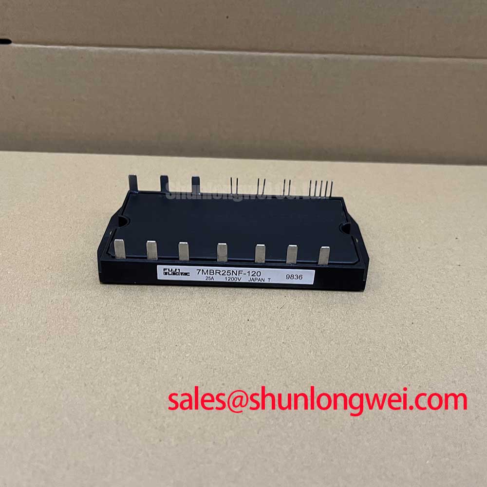
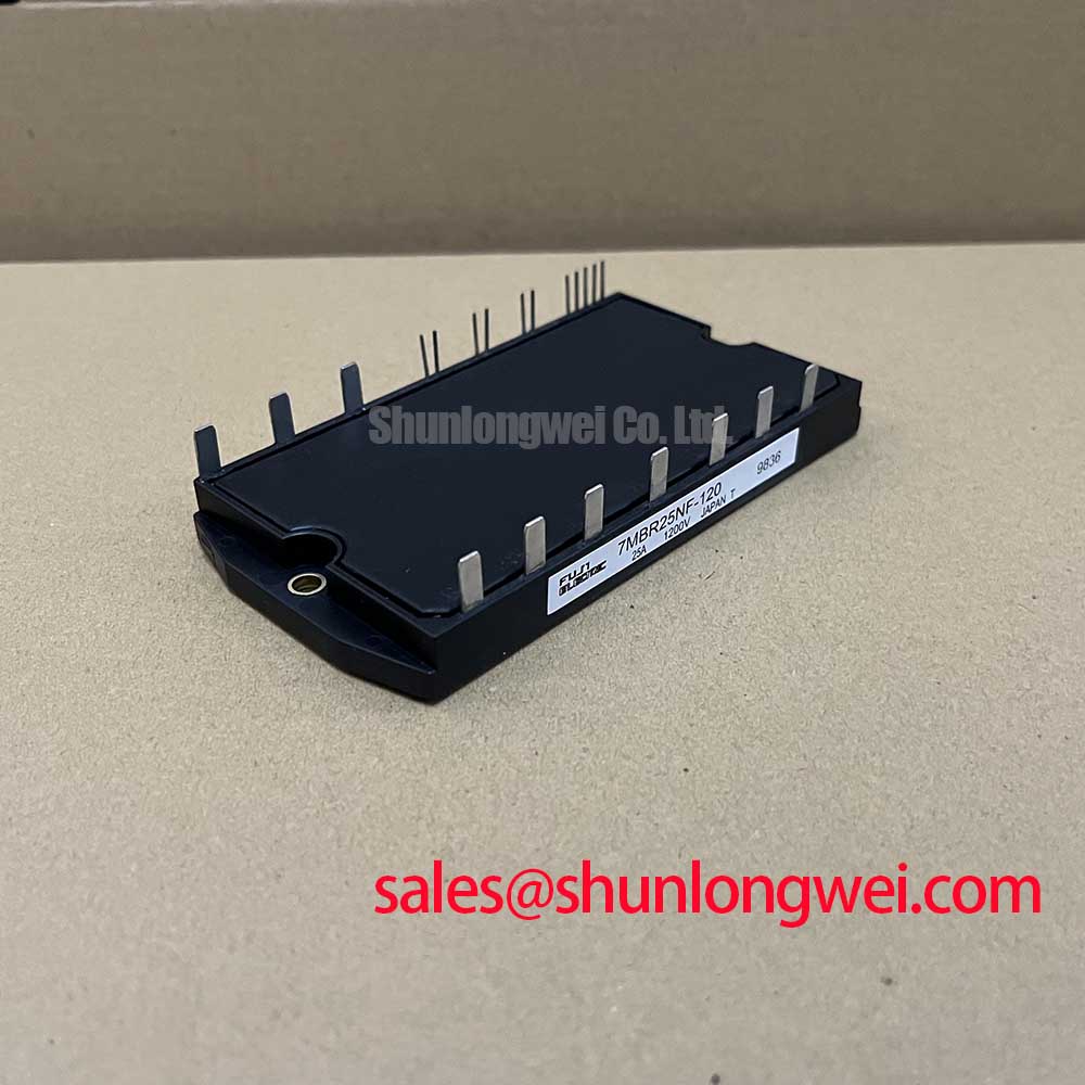
The Fuji Electric 7MBR25NF-120 is a highly integrated Power Integrated Module (PIM) that consolidates a three-phase inverter, a brake chopper, and a converter diode bridge into a single compact package. This 7-in-1 configuration provides a streamlined solution for engineers developing low-power motor control systems, significantly reducing component count and simplifying PCB layout.
- Core Specifications: 1200V | 25A | P-C 200W
- Key Advantages: Simplifies assembly, reduces system size, includes on-board temperature sensing.
- Design Benefit: The integrated brake circuit allows for effective energy dissipation during motor deceleration, a frequent requirement in servo applications.
Download Official Datasheet (PDF)
Technical Analysis of the 7-in-1 Power Stage
The primary value of the 7MBR25NF-120 lies in its high level of integration. By combining seven IGBTs and their corresponding freewheeling diodes into one module, it replaces numerous discrete components. This PIM vs. discrete IGBT approach accelerates the design cycle for variable frequency drives (VFDs) and servo systems. The module includes a three-phase bridge for motor control and an additional chopper IGBT for dynamic braking. This built-in braking circuit is crucial for applications that require controlled and rapid deceleration without causing DC bus overvoltage.
On-Board Thermal Management and Reliability
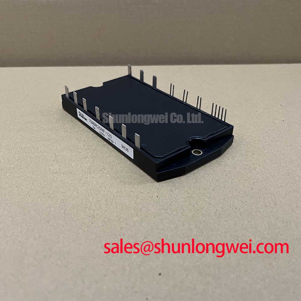
Effective thermal management is fundamental to power module longevity. The 7MBR25NF-120 features an integrated NTC thermistor, providing a direct method for monitoring the module’s internal temperature. This real-time feedback enables the control system to implement over-temperature protection, preventing thermal runaway and enhancing overall system reliability. The module’s thermal resistance from junction to case (Rth(j-c)) for the inverter IGBT is specified at 1.0°C/W (max). You can think of thermal resistance as the width of a pipe for heat; a lower value means a wider pipe, allowing heat to flow more easily from the silicon die to the heatsink and preventing overheating under load.
Optimized Application Scenarios
The specific feature set of the 7MBR25NF-120 makes it a strong candidate for several applications:
- Small Industrial Motor Drives: The 7-in-1 integration drastically reduces the footprint and assembly complexity for compact VFDs under 5 kW.
- AC Servo Amplifiers: The built-in brake chopper is essential for handling the regenerative energy produced during fast positioning and deceleration cycles.
- HVAC Systems: Its power rating is well-suited for compressors and fan motors, where efficiency and compact design are valued.
- Uninterruptible Power Supplies (UPS): The module’s robust 1200V rating and integrated components provide a solid foundation for the inverter stage.
This module is best matched for low-power drive systems where reducing physical size and simplifying manufacturing are primary engineering goals.
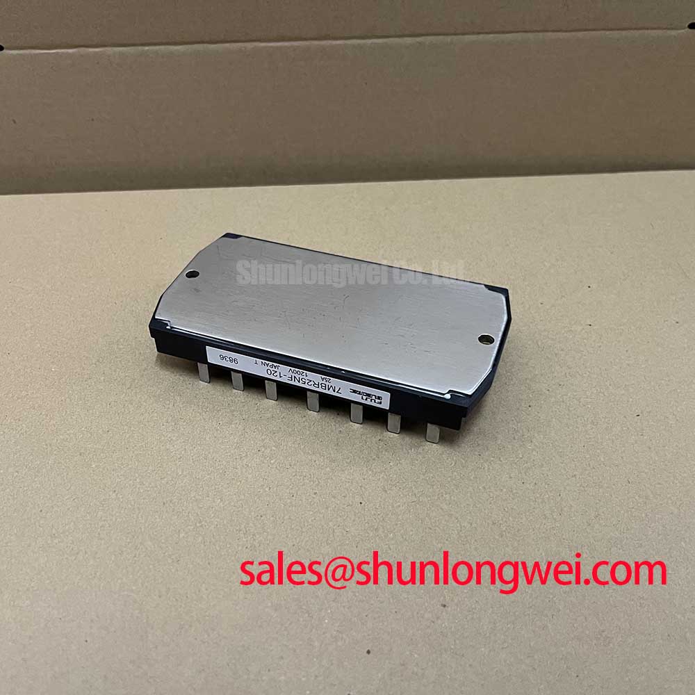
Key Specifications of the 7MBR25NF-120
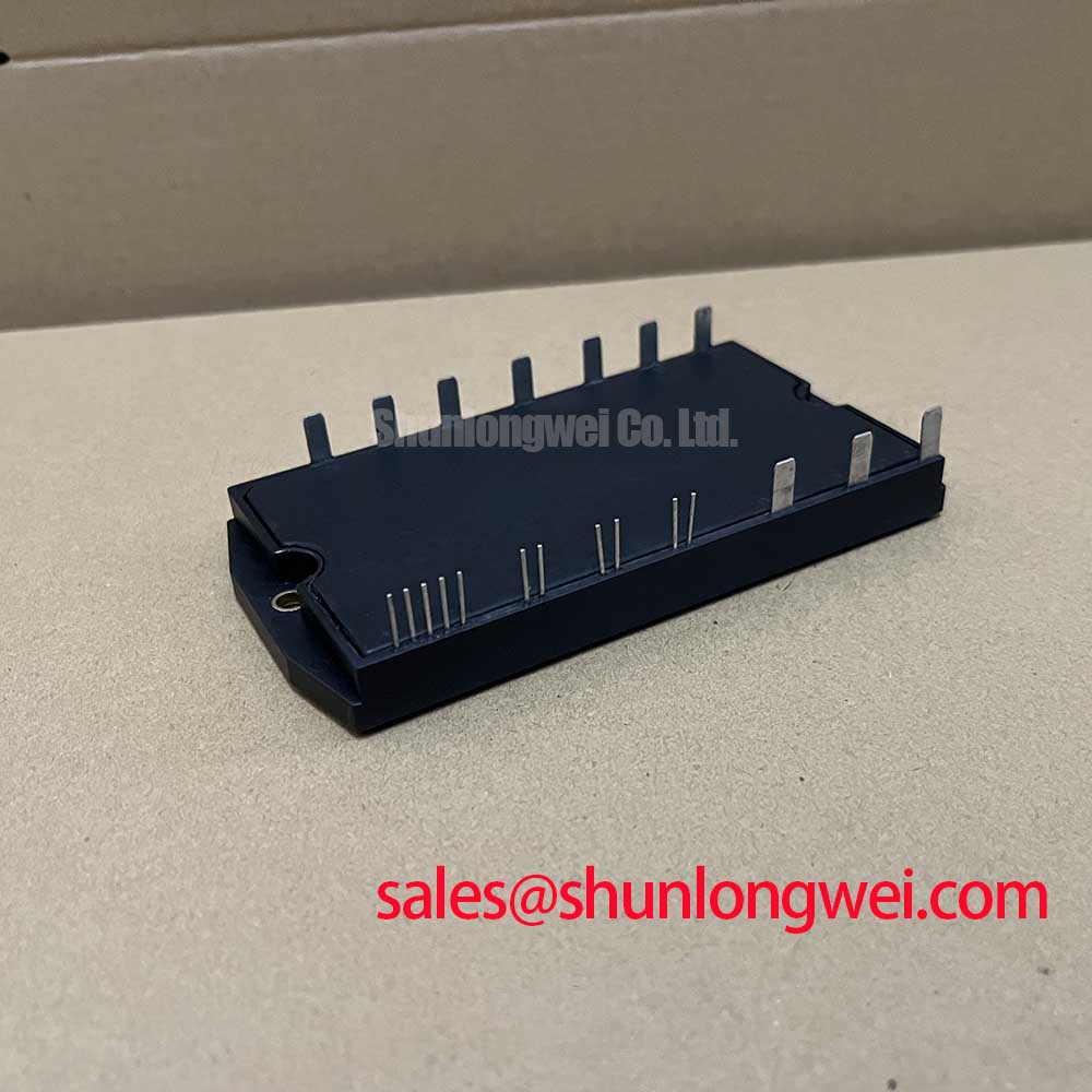
| Absolute Maximum Ratings (Tj = 150°C unless otherwise noted) | |
|---|---|
| Collector-Emitter Voltage (Vces) | 1200V |
| Gate-Emitter Voltage (Vges) | ±20V |
| Collector Current (Ic) @ Tc=25°C | 25A |
| Max Power Dissipation (Pc) | 200W |
| Electrical Characteristics (Tj = 25°C) | |
| Collector-Emitter Saturation Voltage (VCE(sat)) | 2.7V (Max) @ Ic=25A |
| FWD Forward Voltage (VF) | 2.7V (Max) @ Ie=25A |
| Gate-Emitter Threshold Voltage (VGE(th)) | 5.0V to 8.0V |
Engineer’s FAQ
What is the main advantage of the 7MBR25NF-120’s “7-in-1” configuration?
The primary benefit is system simplification. It integrates the complete power stage for a three-phase inverter with a dynamic brake chopper into one component. This reduces the bill of materials (BOM), shrinks the required PCB area, and minimizes assembly time and potential points of failure compared to a discrete solution.
How should the integrated NTC thermistor be used for thermal protection?
The NTC thermistor provides resistance that changes predictably with temperature. Engineers should connect it to a monitoring circuit (e.g., a voltage divider feeding an ADC on a microcontroller). By referencing the resistance-temperature curve in the datasheet, the controller can accurately track the module’s case temperature and trigger a fault or de-rate the output current if it exceeds the safe operating limit (e.g., 125°C).
What are the recommended gate drive voltage conditions?
According to the datasheet, the recommended gate-emitter voltage (VGE) for turning the IGBTs on is +15V (with a tolerance of ±2V). For turn-off, 0V is standard, although a negative voltage (e.g., -5V to -10V) can be used to improve noise immunity and prevent parasitic turn-on, a topic further explored in our guide on enhancing IGBT noise immunity.
How critical is heatsink selection and mounting for this module?
Proper thermal design is crucial for any power module. The baseplate must be mounted to a flat, clean heatsink using a thin, uniform layer of thermal grease. The datasheet specifies a mounting torque of 2.5-3.5 Nm for the M5 screws. Inadequate mounting can create voids, increasing thermal resistance and leading to premature failure. Calculating the required heatsink performance is a key step in ensuring system reliability.
Enabling Efficient Power Conversion
The 7MBR25NF-120 power module offers a robust, all-in-one solution that directly addresses the challenges of designing compact and reliable motor control systems. Its high level of integration, combined with essential protective features, empowers engineers to develop efficient power conversion hardware with a faster time-to-market.