Fuji 7MBR50SB120: A Technical Review of the 1200V 50A IGBT Module
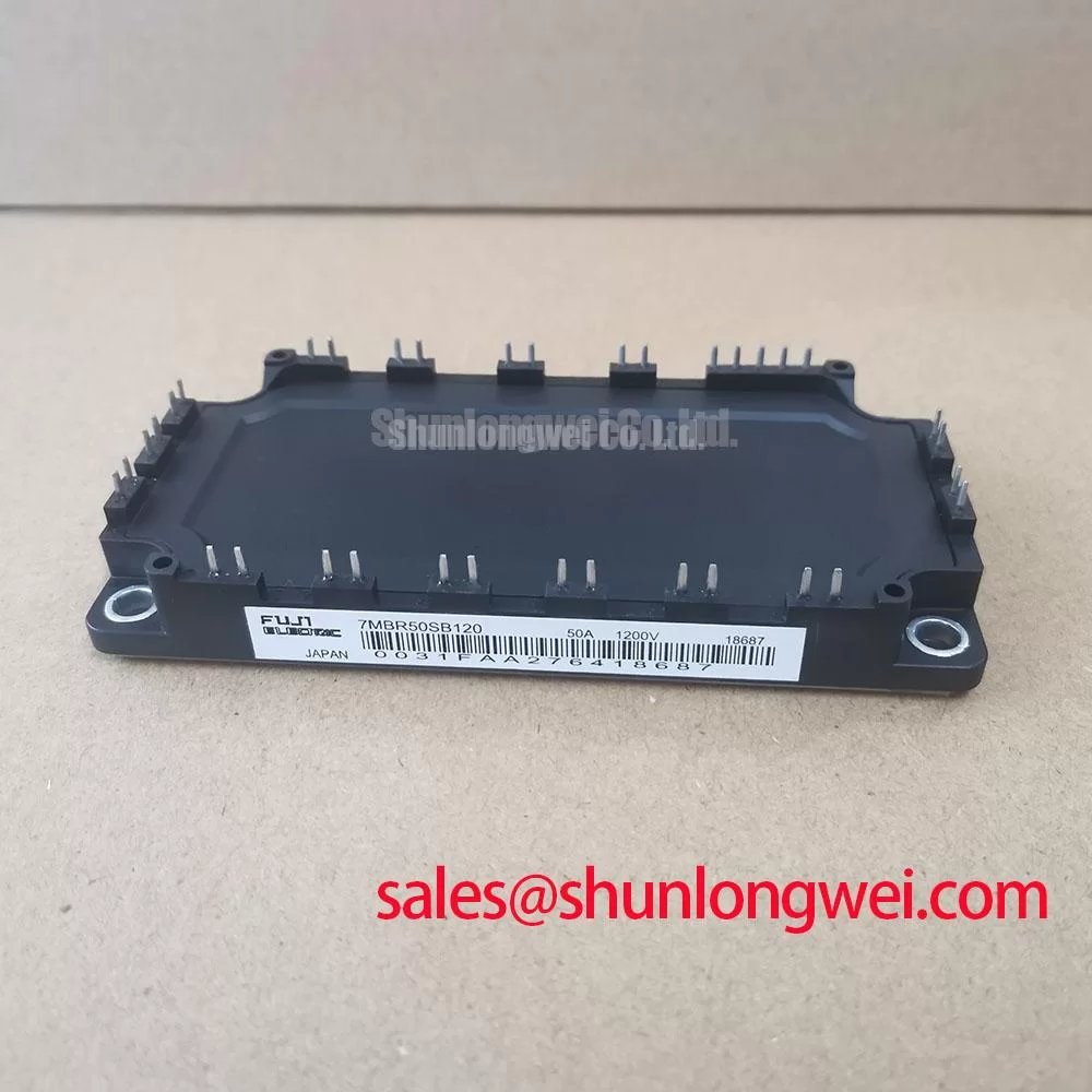
7MBR50SB120 Fuji Electric 1200V 50A PIM IGBT Module
Introduction to the 7MBR50SB120 Power Integrated Module
The Fuji Electric 7MBR50SB120 is a Power Integrated Module (PIM) that consolidates a complete three-phase inverter stage, including a brake chopper, into a single compact component. This module’s primary engineering value is its ability to reduce conduction losses and simplify the overall system design. By integrating seven N-channel IGBTs, it offers a streamlined solution for motor control and power conversion applications where efficiency and space are critical design parameters.
- Core Specifications: 1200V | 50A | 7-in-1 Module
- Key Advantages: Low VCE(sat) minimizes heat dissipation. An integrated NTC thermistor enables precise thermal monitoring.
This integrated approach not only reduces component count but also provides a centralized thermal source, which simplifies the process of calculating heat dissipation for proper heatsink selection.
Download Official Datasheet (PDF)

Technical Analysis for System Integration
A defining characteristic of the 7MBR50SB120 is its low collector-emitter saturation voltage (VCE(sat)). This parameter is crucial for system efficiency. You can think of VCE(sat) as the electrical “friction” the switch creates when it’s on; a lower value signifies less friction. With a typical VCE(sat) of 2.1V at its nominal current, this module converts less electrical energy into waste heat during operation. This directly leads to lower cooling requirements, allowing for smaller, more cost-effective heatsink designs and improved overall system reliability.
The module also includes a built-in NTC thermistor, providing a direct and accurate way to monitor the device’s operating temperature. This is far more precise than attaching an external sensor to the heatsink. Accurate thermal feedback is essential for implementing robust over-temperature protection. It allows the control system to reduce current or shut down gracefully if the module approaches its maximum junction temperature of 150°C, a key factor in preventing component failure. For more details on this topic, see our guide to the role of integrated NTCs in IGBT reliability.

Optimized Application Scenarios
The specific configuration and performance metrics of the 7MBR50SB120 make it a strong candidate for several power conversion applications.
- AC Motor Drives: Its 7-in-1 topology (six-pack inverter plus brake chopper) is a standard requirement for variable frequency drives (VFDs), simplifying the power stage design.
- AC and DC Servo Drive Amplifiers: The module’s characteristics support the dynamic and precise control needed in high-performance servo systems.
- Uninterruptible Power Supplies (UPS): The integration and thermal efficiency are beneficial for the inverter stage of UPS systems, contributing to higher reliability.
- General Purpose Inverters: The robust voltage and current ratings provide ample margin for various industrial inverter designs.
This module is best matched for three-phase inverter systems up to 22kW, where its balance of performance, integration, and thermal efficiency delivers significant value.
Key Specifications of the 7MBR50SB120
| Absolute Maximum Ratings (at Tc=25°C) | |
|---|---|
| Collector-Emitter Voltage (VCES) | 1200V |
| Gate-Emitter Voltage (VGES) | ±20V |
| Inverter Collector Current (Ic) | 50A (at Tc=80°C) |
| Inverter Collector Current (Pulsed) (Icp) | 100A |
| Max Power Dissipation (Pc) | 280W (per IGBT) |
| Electrical Characteristics (at Tvj=25°C) | |
| Collector-Emitter Saturation Voltage (VCE(sat)) | 2.1V (typ.) / 2.7V (max) |
| Gate Threshold Voltage (VGE(th)) | 5.5V (typ.) |
| FWD Forward Voltage (VF) | 2.0V (typ.) / 2.6V (max) |
| Thermal and Mechanical Characteristics | |
| Operating Junction Temperature (Tj) | +150°C |
| Thermal Resistance, Junction-to-Case (Rth(j-c)) | 0.45 K/W (per IGBT) |
| Mounting Screw Torque | 2.5 – 3.5 Nm |
Engineer’s Frequently Asked Questions
1. How should I calculate the required heatsink performance for the 7MBR50SB120?
To determine the heatsink requirement, first calculate the total power loss (conduction and switching losses) based on your application’s specific operating conditions (current, voltage, switching frequency, and duty cycle). The datasheet provides the necessary curves and values. Then, use the module’s thermal resistance (Rth(j-c)) to find the maximum allowable case-to-ambient thermal resistance for the heatsink to keep the junction temperature below 150°C.
2. What are the best practices for mounting this PIM to a heatsink?
Ensure the heatsink surface is flat, clean, and free of burrs. Apply a thin, even layer of quality thermal compound across the module’s isolated baseplate. Mount the module using the specified screw torque (2.5 – 3.5 Nm). Uneven torque can lead to poor thermal contact and mechanical stress on the module.
3. What is the benefit of the integrated brake chopper in this module?
The integrated brake chopper provides a ready-made circuit for dynamic braking in motor drive applications. When a motor decelerates, it acts as a generator, sending voltage back to the DC bus. The chopper circuit dissipates this regenerative energy through an external braking resistor, preventing DC bus overvoltage faults.
Enabling Efficient Power System Design
The 7MBR50SB120 from Fuji Electric is an engineered solution for power conversion that prioritizes efficiency and integration. By combining a low VCE(sat) with an integrated structure and essential thermal feedback, this Power Integrated Module gives designers the tools to build compact, reliable, and thermally stable motor control systems.