Fuji Electric 2MBI400VG-60: High-Efficiency 600V 400A V-Series IGBT Module Technical Overview
Fuji Electric 2MBI400VG-60 | 600V 400A V-Series IGBT Module
Introduction and Core Technical Highlights
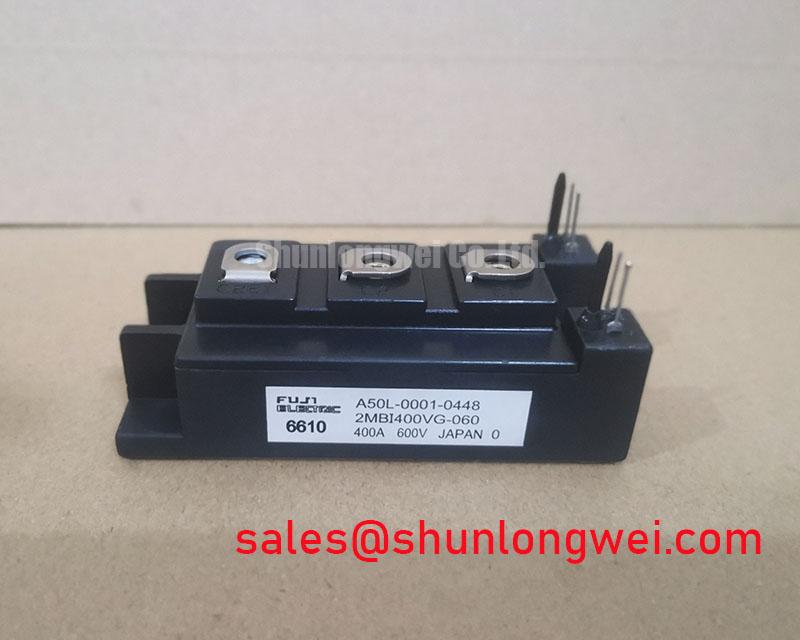
The 2MBI400VG-60 is a high-performance 600V, 400A dual IGBT module utilizing Fuji Electric’s advanced 6th-generation V-Series trench technology. This module is engineered to provide superior power density and thermal management for industrial power conversion systems. By significantly lowering the collector-emitter saturation voltage, this module achieves a unique value proposition: drastic reduction in conduction losses without compromising high-speed switching capabilities.
- Core Specifications: 600V | 400A | VCE(sat) 1.70V (Typical)
- Key Advantage: Exceptional thermal resilience with a maximum junction temperature (Tj) of 175°C, allowing for higher power throughput in compact enclosures.
- Design Efficiency: Optimized package inductance and simplified gate drive requirements facilitate easier integration into half-bridge and three-phase inverter topologies.
For engineers seeking to calculate the exact power loss under specific duty cycles, understanding the trade-off between conduction and switching losses is essential. The 2MBI400VG-60 addresses this by providing a stable VCE(sat) curve across its operating temperature range.
Download Official 2MBI400VG-60 Datasheet (PDF)
Technical Analysis: Efficiency Through Trench Technology
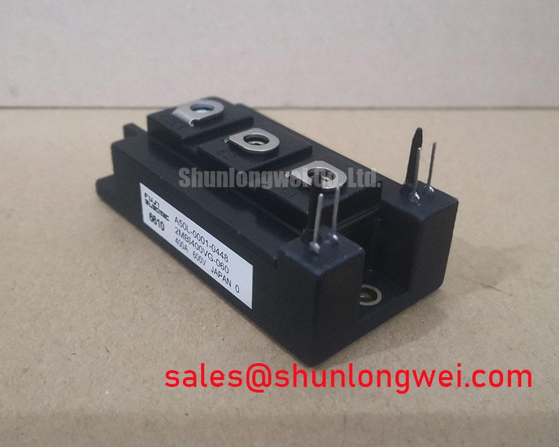
The evolution of Trench Gate technology within the V-Series is the foundation of the 2MBI400VG-60’s performance. By refining the trench structure, Fuji Electric has managed to minimize the internal resistance of the silicon die. This results in a typical VCE(sat) of 1.70V at 400A. In engineering terms, this means lower heat generation during the “on” state, which directly translates to reduced cooling requirements and smaller heatsink profiles.
To understand the importance of saturation voltage, one can use a simple hydraulic analogy: imagine VCE(sat) as the pressure drop across a valve. A high pressure drop (high voltage) means the system is working harder and wasting energy as heat. The 2MBI400VG-60 functions as a “wide-bore” valve, allowing current to flow with minimal resistance, thereby preserving system efficiency. Furthermore, proactive monitoring can prevent catastrophic failures by analyzing IGBT failure mechanisms such as bond-wire fatigue or thermal runaway.
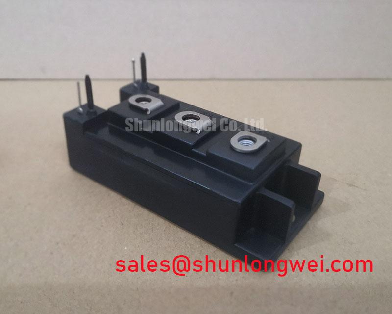
Thermal management is another critical area where this module excels. The junction-to-case thermal resistance (Rth(j-c)) for the IGBT is rated at a maximum of 0.085 °C/W. Achieving long-term reliability in heavy-duty applications requires mastering IGBT thermal design, specifically focusing on the junction-to-ambient heat path to ensure the module stays within its 175°C peak temperature limit.
Optimized Application Scenarios
- Industrial Inverters: High current rating (400A) allows for robust operation in motor drive applications where high torque and rapid acceleration are required.
- Uninterruptible Power Supplies (UPS): Low conduction losses ensure higher battery efficiency and longer runtime during critical power transitions.
- Welding Machines: The 2MBI400VG-60’s ability to handle high pulsed currents (800A peak) makes it ideal for the demanding duty cycles of industrial welding.
- Solar Power Inverters: Optimized for 600V DC links, providing a reliable switching platform for medium-scale renewable energy systems.
Best Match: Superior for high-duty 600V systems requiring 400A continuous current with minimal conduction-related energy waste and simplified thermal system design.
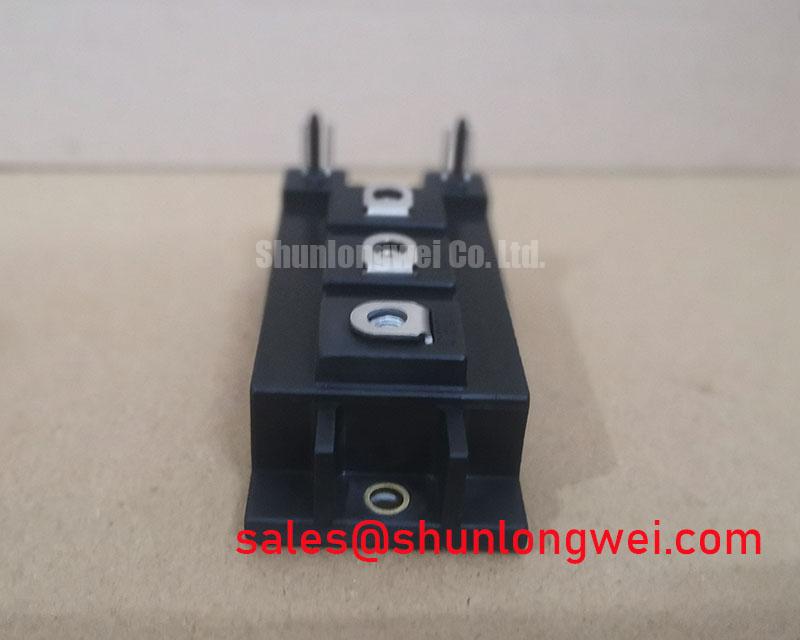
Key Specifications Table
| Category | Parameter | Symbol | Rating / Value |
|---|---|---|---|
| Absolute Maximum Ratings | Collector-Emitter Voltage | VCES | 600V |
| Continuous Collector Current (Tc=80°C) | IC | 400A | |
| Junction Temperature | Tj | 175°C (Max) | |
| Electrical Characteristics (Tj=25°C) | Gate-Emitter Threshold Voltage | VGE(th) | 6.5V (Typical) |
| Collector-Emitter Saturation Voltage | VCE(sat) | 1.70V (Typical) | |
| Total Gate Charge | Qg | 1800 nC (Typical) | |
| Thermal Characteristics | IGBT Thermal Resistance (Junction to Case) | Rth(j-c) | 0.085 °C/W (Max) |
| FWD Thermal Resistance (Junction to Case) | Rth(j-c) | 0.15 °C/W (Max) |
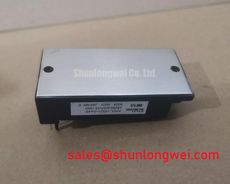
Engineer FAQ
Q1: What is the significance of the 175°C junction temperature for the 2MBI400VG-60?
A: The increased Tj(max) allows for a wider design margin. Engineers can either run the module at higher power densities or use more modest cooling solutions while maintaining high reliability in fluctuating load conditions.
Q2: How should I calculate the maximum power loss for this module in my inverter design?
A: You must sum the conduction losses (calculated using IC and VCE(sat) at operating temperature) and the switching losses (Eon and Eoff from the datasheet curves). Ensure the total dissipation does not exceed the limit set by your heatsink’s thermal resistance.
Q3: Are there specific mounting considerations for this M235 package?
A: Yes. For optimal heat transfer, ensure the baseplate is applied with a uniform layer of thermal grease. The recommended mounting torque for the M5 terminals and the module itself should be strictly adhered to as per Fuji Electric’s application notes to avoid mechanical stress on the ceramic substrate.
Closing Statement
The Fuji Electric 2MBI400VG-60 represents a pinnacle of efficiency for 600V power systems. By leveraging V-Series trench technology to drive down conduction losses, it empowers engineers to build more sustainable, compact, and powerful converters. Whether integrated into a variable frequency drive or a high-capacity UPS, this module provides the technical foundation for robust power switching and long-term industrial reliability.