Fuji Electric 2MBI75U4A-120-50: 1200V 75A Dual IGBT Module Technical Overview
2MBI75U4A-120-50 Fuji Electric 1200V 75A Dual IGBT Module
Introduction and Core Highlights
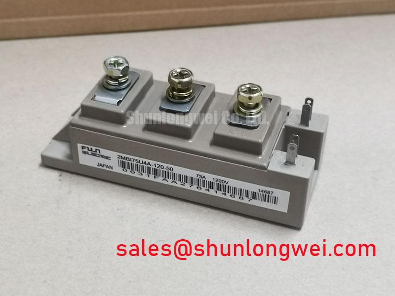
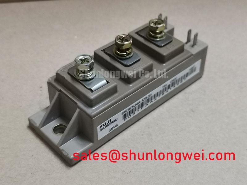
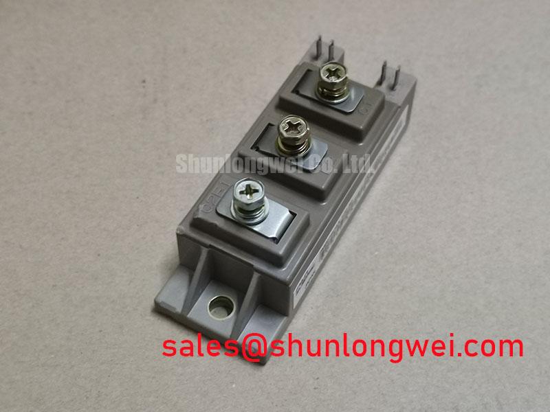
The Fuji Electric 2MBI75U4A-120-50 is a dual-channel power module utilizing trench-gate field-stop IGBT technology. Built in a half-bridge topology, this module is optimized for high-power switching applications requiring high thermal efficiency and minimized electrical losses.
- Core Specifications: 1200V rated collector-emitter voltage, 75A collector current at a case temperature of 80°C, and a typical saturation voltage ($V_{CE(sat)}$) of 1.90V.
- Key Engineering Benefits: Decreased thermal load on system cooling and reduced gate drive power requirements due to optimized gate charge characteristics.
- Design Intention: This module resolves conduction loss challenges by utilizing a trench structure that lowers collector-emitter saturation voltage during continuous operation.
Download Official 2MBI75U4A-120-50 Datasheet (PDF)
Technical Analysis and Engineering Design
The design of the 2MBI75U4A-120-50 prioritizes power efficiency and thermal ruggedness. By utilizing a trench-gate structure, the module optimizes charge carrier distribution within the drift region. This technology lowers the collector-emitter saturation voltage ($V_{CE(sat)}$) during conduction, directly decreasing static power losses. For details on how this design improves system efficiency, refer to the technical analysis of trench gate evolution.
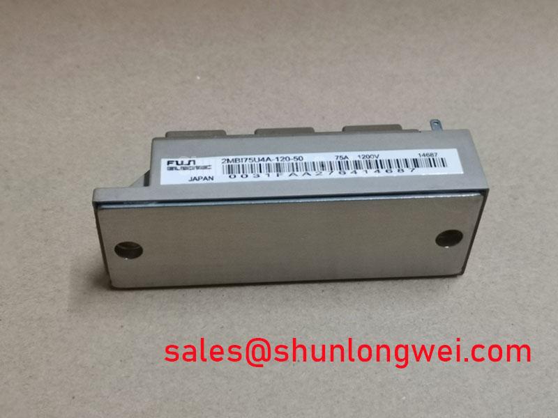
Furthermore, the module features an isolated copper baseplate. This configuration enhances heat transfer to the system’s cooling assembly. You can think of the thermal resistance ($R_{th(j-c)}$) as a water pipe; a wider pipe (lower thermal resistance) allows heat to flow away from the junction much faster. This keeps the junction temperature within safe limits during transient overloads. You can read more about this mechanical layer in the guide on isolated baseplates.
Finally, the internal structural layout prevents dynamic latch-up effects. By controlling the gain of the parasitic thyristor, the module remains stable under high voltage gradients ($dv/dt$). Understanding how to avoid these conditions is critical for motor drive safety, as explained in our review of preventing IGBT latch-up.
Optimized Application Scenarios
- AC and DC Servo Drive Amplifiers: The fast switching speed and low turn-off energy loss enable precise positioning control with minimal thermal overhead.
- Variable Frequency Drives (VFDs): The 1200V collector-emitter voltage rating provides robust insulation safety margins for 400V/480V AC line voltages.
- Uninterruptible Power Supplies (UPS): Low conduction loss optimizes inverter conversion efficiency during battery backup operation.
Best Match: The 2MBI75U4A-120-50 is suitable for industrial power converters operating up to 20 kHz with a continuous collector current limit of 75A.
Key Specifications Parameter Table
| Category | Parameter | Typical Value | Maximum Rating |
|---|---|---|---|
| Absolute Maximums | Collector-Emitter Voltage ($V_{CES}$) | – | 1200 V |
| Gate-Emitter Voltage ($V_{GES}$) | – | ±20 V | |
| Collector Current ($I_C$ continuous, $T_C=80^circ$C) | – | 75 A | |
| Electrical Characteristics | Collector-Emitter Saturation Voltage ($V_{CE(sat)}$, $T_j=25^circ$C) | 1.90 V | 2.35 V |
| Diode Forward Voltage ($V_F$, $T_j=25^circ$C) | 1.90 V | 2.40 V | |
| Gate Threshold Voltage ($V_{GE(th)}$) | 6.5 V | 7.5 V | |
| Thermal Characteristics | Thermal Resistance, Junction-to-Case (IGBT) | – | 0.35 °C/W |
| Thermal Resistance, Junction-to-Case (Diode) | – | 0.60 °C/W |
Engineer FAQ
Q1: What is the recommended gate resistance ($R_g$) for the 2MBI75U4A-120-50?
A1: The datasheet references a nominal testing gate resistance of 16 Ω. In actual designs, the gate resistor value should be tuned to balance switching losses against collector-emitter voltage turn-off spikes.
Q2: How does temperature affect the saturation voltage of the 2MBI75U4A-120-50?
A2: The module exhibits a positive temperature coefficient. The typical $V_{CE(sat)}$ rises from 1.90V at 25°C to 2.20V at 125°C under rated current conditions. This behavior supports stable thermal performance when paralleling multiple modules.
Q3: How do I prevent overvoltage failures during inductive load turn-off?
A3: Keep the loop inductance between the DC-link capacitors and the module terminals as low as possible. A low-inductance busbar and a localized snubber capacitor should be used to clamp the peak transient voltage spike.
Concluding Statement
This power module provides a balanced combination of low conduction losses and robust thermal design. Utilizing Trench-gate Field-stop technology, the 2MBI75U4A-120-50 enables engineers to develop compact, high-efficiency power stages for demanding industrial systems.