Fuji Electric 6MBI450UM-170 IGBT Module: 1700V 450A Technical Analysis and Application Guide
6MBI450UM-170 Fuji Electric IGBT Module | 1700V 450A Inverter
The 6MBI450UM-170 is a high-power industrial IGBT module belonging to Fuji Electric’s U-Series, specifically engineered for high-voltage inverter applications. Utilizing advanced trench-gate technology, this 6-pack module delivers a Unique Value Proposition by maximizing power density while maintaining a low collector-emitter saturation voltage ($V_{CE(sat)}$). This efficiency is critical for engineers aiming to reduce thermal overhead in 1700V systems without compromising on switching speeds or ruggedness.
- Core Specifications: 1700V Collector-Emitter Voltage | 450A Continuous Collector Current | $V_{CE(sat)}$ typical 2.2V.
- Key Engineering Benefits: Significant reduction in conduction losses and a simplified gate drive design architecture.
- Addressing Design Challenges: To mitigate the common issue of voltage spikes during high-speed switching, the 6MBI450UM-170 is designed with a low-inductance internal layout, helping to minimize EMI and stress on the semiconductor chips.
Download Official Datasheet (PDF)
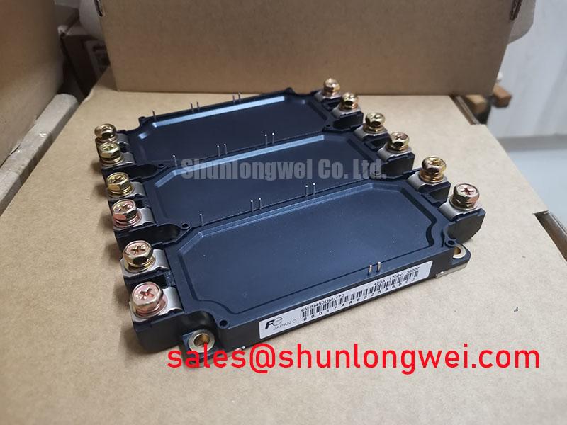
Technical Analysis: Efficiency and Thermal Dynamics
The engineering significance of the 6MBI450UM-170 lies in its balance between $V_{CE(sat)}$ and switching characteristics. In 1700V systems, conduction losses can escalate rapidly at higher currents. By keeping the saturation voltage low, Fuji Electric ensures that the power dissipated as heat is minimized. This effectively reduces the physical size requirements for cooling systems, such as heatsinks and forced-air fans.
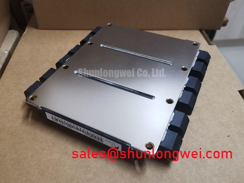
To understand the importance of thermal resistance ($R_{th(j-c)}$) in this module, one can use a simple analogy: think of thermal resistance as the narrowness of a drain pipe. A lower resistance value acts like a wider pipe, allowing heat to flow away from the transistor junction to the baseplate much more easily. This prevents “heat congestion” that could lead to thermal runaway or premature device failure. For high-current switching, understanding the Zth curve provided in the technical documentation is essential for accurate peak temperature modeling.
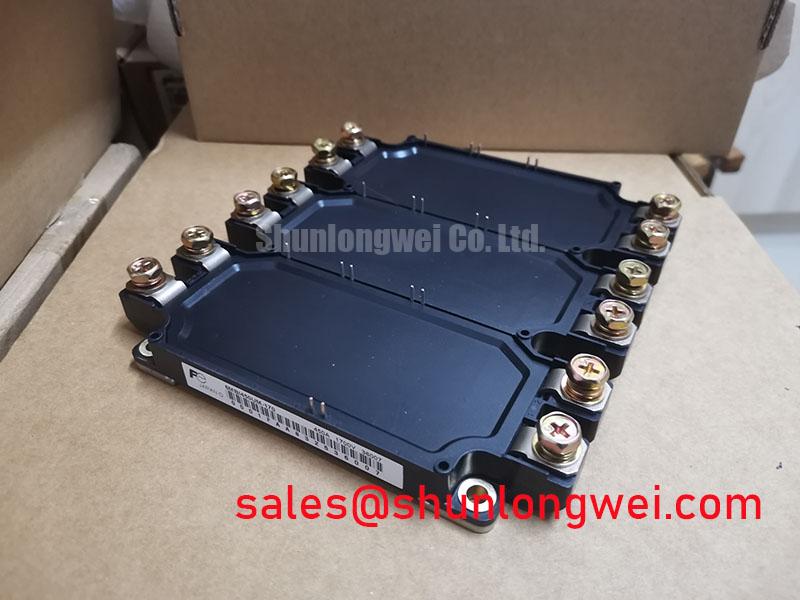
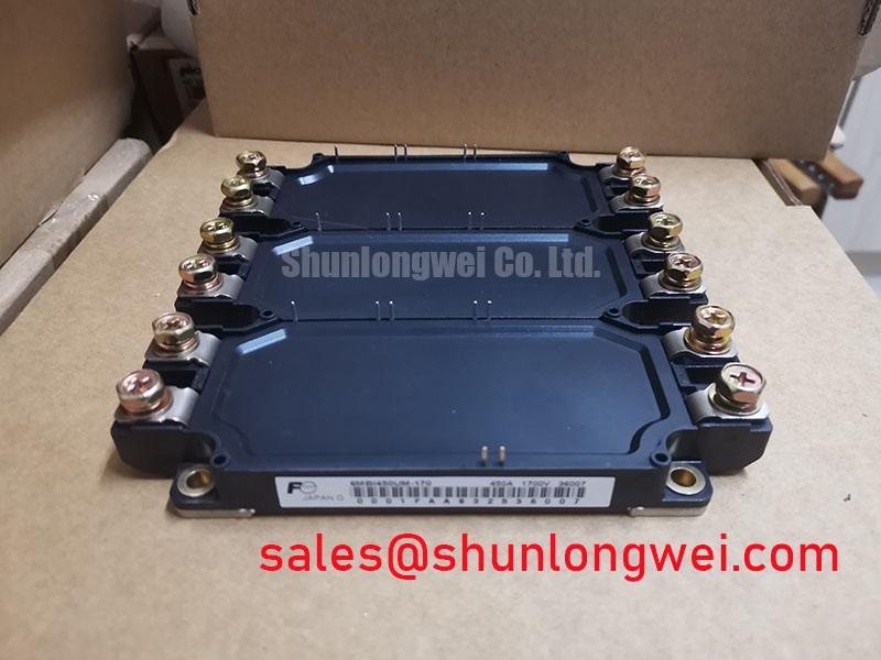
Furthermore, the 6MBI450UM-170 addresses parasitic inductance through its optimized internal busbar geometry. In high-power modules, stray inductance can cause damaging voltage overshoots during turn-off. The U-Series construction reduces these internal loop areas, providing a cleaner switching waveform and allowing for faster $dv/dt$ transitions without requiring excessively large snubber circuits.
Optimized Application Scenarios
The robust 1700V rating makes this module suitable for environments where grid voltage fluctuations or high DC link voltages are present. Below are primary use cases for the 6MBI450UM-170:
- Variable Frequency Drives (VFD): Ideal for heavy-duty motor control where high start-up torque and 450A current handling are required.
- Renewable Energy Inverters: Perfect for wind power converters and large-scale solar central inverters that operate on higher DC bus voltages.
- Uninterruptible Power Supplies (UPS): Supports high-reliability energy conversion in data centers where thermal consistency is mandatory.
- Industrial Welding Power Supplies: The module’s high switching frequency capability ensures precise arc control and stability.
Best Match Conclusion: This module is the optimal choice for designs requiring a compact 6-pack inverter configuration with a 1700V safety margin and 450A capacity.
Key Specifications and Ratings
| Category | Parameter | Value |
|---|---|---|
| Absolute Max Ratings | Collector-Emitter Voltage ($V_{CES}$) | 1700 V |
| Collector Current ($I_C$ Continuous) | 450 A | |
| Junction Temperature ($T_j$) | Up to 150°C | |
| Electrical Characteristics | Saturation Voltage ($V_{CE(sat)}$) | 2.2 V (Typ) |
| Gate Threshold Voltage ($V_{GE(th)}$) | 4.5 V – 8.5 V | |
| Isolation & Thermal | Isolation Voltage ($V_{iso}$) | 3400 V (AC 1 min) |
| Thermal Resistance ($R_{th(j-c)}$ IGBT) | 0.032 °C/W |

Engineer’s FAQ
Q1: What is the recommended gate resistor ($R_G$) for the 6MBI450UM-170?
A1: The datasheet specifies a typical gate resistance for optimal switching performance. For 1700V operations, $R_G$ should be selected to balance switching speed against $V_{CE}$ overshoot. Always consult the $E_{on}/E_{off}$ vs. $R_G$ curves in the manufacturer’s documentation.
Q2: How should I calculate the total power loss for thermal management sizing?
A2: Total power loss is the sum of conduction loss ($I_C times V_{CE(sat)}$) and switching losses ($E_{on} + E_{off} times frequency$). Ensure you account for the duty cycle and the worst-case junction temperature to prevent thermal overload.
Q3: Does this module include an integrated temperature sensor?
A3: Most U-Series modules in this power class include an integrated NTC thermistor for real-time temperature monitoring. Please refer to the specific 6MBI450UM-170 pinout diagram to locate the thermistor terminals for your protection circuitry.
The 6MBI450UM-170 offers a stable platform for high-voltage power conversion, leveraging Fuji’s proven trench technology to ensure long-term reliability in demanding industrial environments. By providing superior current handling and low thermal resistance, it empowers engineers to design high-efficiency power stages with a high degree of confidence.