Fuji Electric 7MBR75VZ120-50 1200V 75A PIM IGBT Module: Technical Analysis and Applications
Fuji Electric 7MBR75VZ120-50 1200V 75A PIM IGBT Module
Introduction and Core Product Capabilities
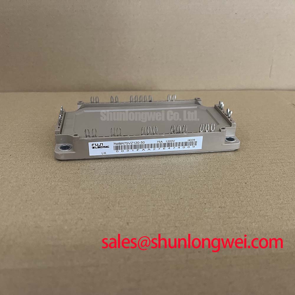
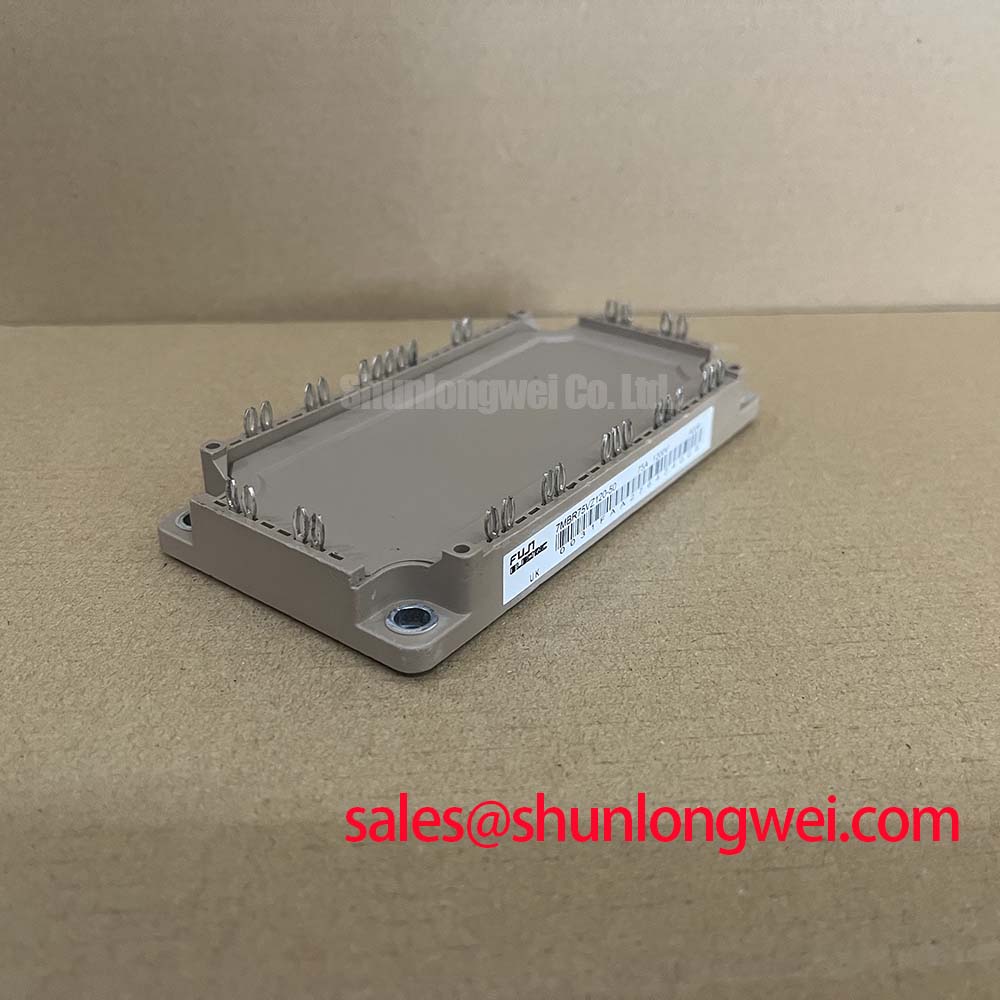
The 7MBR75VZ120-50 is a highly integrated 1200V, 75A Power Integrated Module (PIM) designed by Fuji Electric. This module consolidates a three-phase input rectifier, a three-phase inverter bridge, a brake chopper, and a temperature-sensing thermistor into a single compact housing. This layout significantly reduces PCB complexity and mitigates the impact of parasitic inductance in high-power setups.
- Ratings: 1200V collector-emitter voltage and 75A continuous collector current.
- Integrated NTC: Built-in thermistor ensures real-time temperature tracking near the silicon chips.
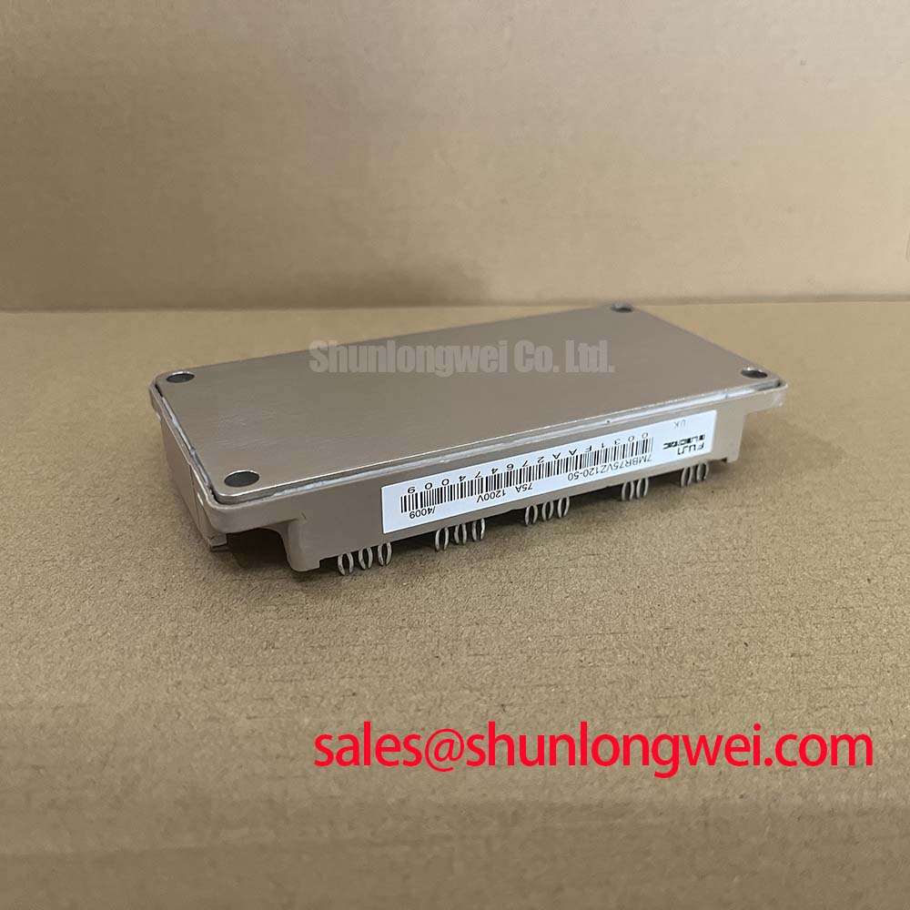
- Enhanced Packaging: Solderable pins provide a durable connection for demanding industrial applications.
How does the integrated layout protect the system from thermal damage? By housing the thermistor on the same substrate as the silicon dies, engineers get instantaneous temperature feedback. This allows gate drivers to initiate rapid shutdown protocols before destructive thermal runaway occurs.
Download Official Fuji Electric V-Series IGBT Application Note (PDF)
Technical Analysis and Thermal Design
The 7MBR75VZ120-50 utilizes Trench Gate Field Stop technology to lower the collector-emitter saturation voltage ($V_{CE(sat)}$) to a typical value of 1.70V. Lowering saturation voltage directly decreases conduction losses during high-current periods. When evaluating a PIM vs. discrete IGBT topology, this unified module optimizes the internal wire bond placement, maintaining symmetrical current distribution and minimizing switching oscillations.
Thermal management is highly efficient due to the direct-bonded copper (DBC) substrate. The junction-to-case thermal resistance ($R_{th(j-c)}$) is restricted to 0.33°C/W per IGBT. To understand this, think of thermal resistance as a narrow pipe; a smaller value represents a wider pipe, allowing heat to escape quickly to the heatsink. This rapid heat transfer keeps the junction temperature ($T_j$) safely below its absolute maximum of 150°C during transient overload states.
For optimal switching speed and noise suppression, engineers must focus on the gate drive design. Correctly matching the external gate resistor ($R_g$) helps balance switching losses with electromagnetic interference (EMI) levels, ensuring the module functions reliably in noisy industrial environments.
Target Industrial Applications
- Variable Frequency Drives (VFDs): Perfect for regulating industrial AC motors under 15kW where cabinet space is limited.
- Servo Drive Systems: High-frequency switching capability supports precise position and speed control in robotics.
- Solar Inverters: 1200V rating easily manages DC link bus voltages in grid-tied renewable energy systems.
- Uninterruptible Power Supplies (UPS): Fast turn-off times support highly efficient double-conversion topologies.
Best Fit Conclusion: The 7MBR75VZ120-50 delivers the optimal balance of efficiency and footprint for space-constrained three-phase industrial motor control systems under 15kW.
Key Specifications Table
| Parameter Category | Specification Description | Value (Datasheet Fact) |
|---|---|---|
| Absolute Maximums | Collector-Emitter Voltage ($V_{CES}$) | 1200 V |
| Absolute Maximums | Inverter Continuous DC Collector Current ($I_C$) | 75 A (at $T_c$ = 80°C) |
| Absolute Maximums | Repetitive Peak Collector Current ($I_{CP}$) | 150 A |
| Electrical (Inverter) | Collector-Emitter Saturation Voltage ($V_{CE(sat)}$) | 1.70 V (typical at $T_j$ = 25°C, $I_C$ = 75A) |
| Electrical (NTC) | NTC Thermistor Resistance ($R_{25}$) | 5000 Ω (at $T_c$ = 25°C) |
| Thermal Characteristics | IGBT Junction-to-Case Thermal Resistance ($R_{th(j-c)}$) | 0.33 °C/W (per device) |
Engineer FAQ
Q: What is the main benefit of the integrated NTC thermistor in the 7MBR75VZ120-50?
A: The integrated NTC provides direct thermal monitoring of the substrate. This eliminates the delay found with external sensors, allowing the system to react quickly to over-temperature faults.
Q: Why choose a 7-in-1 PIM over discrete IGBT switches?
A: Integrating the rectifier, inverter, and brake chopper into one module simplifies PCB routing, reduces mounting steps, and lowers stray inductance, which stabilizes high-frequency switching.
Q: How do you select the external gate resistor ($R_g$) for this module?
A: Select $R_g$ based on the gate drive requirements shown in the datasheet. A larger $R_g$ decreases dv/dt to help control EMI, while a smaller $R_g$ minimizes switching losses.
Product Design Empowerment
The 7MBR75VZ120-50 PIM is an excellent solution for engineers seeking to design compact, highly reliable motor drives and power converters. By integrating three essential power stages with thermal telemetry, this module simplifies thermal design and reduces assembly overhead. It empowers engineers to meet strict efficiency targets while maintaining a rugged, low-inductance system architecture.