FZ1200R16KF4 Technical Deep Dive: A 1600V/1200A High-Power IGBT Module
## FZ1200R16KF4: A 1600V/1200A High-Power IGBT Module
This Infineon FZ1200R16KF4 is a high-power IGBT module providing a robust solution for high-voltage power conversion systems. It combines a high collector-emitter voltage rating with significant current handling capability in a single-switch configuration. This approach is engineered for efficiency and operational stability in demanding applications.
* **Core Specifications**: 1600V | 1200A | Tvj op 150°C
* **Key Attributes**: High power density in an industry-standard housing, Integrated NTC for thermal monitoring.
* **Engineering Focus**: Facilitates the design of high-voltage inverters where reliable performance under heavy loads is a primary requirement.
Access Datasheet via Third-Party Archive (PDF)
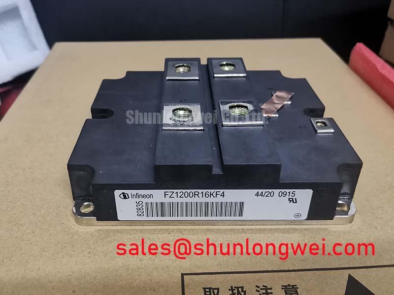


Technical Analysis for High-Voltage Systems
The FZ1200R16KF4 is defined by its capacity to manage substantial power levels. With a repetitive peak collector-emitter voltage (VCES) of 1600V and a nominal DC collector current of 1200A, this module is positioned for use in systems operating well above standard industrial voltages. This high voltage rating provides a necessary safety margin in applications such as large-scale inverters, which can be subject to voltage overshoots and grid instability. The robust design ensures the device operates within its Safe Operating Area (SOA) under demanding conditions.
Efficient heat extraction is fundamental to the reliability of any high-current module. The FZ1200R16KF4 features a low thermal resistance from junction to case (RthJC), a critical parameter for thermal design. Think of thermal resistance like the width of a drainpipe; a lower value signifies a wider pipe that allows heat to flow away from the silicon die more easily. This efficient heat transfer, coupled with a maximum operating junction temperature (Tvj op) of 150°C, allows for effective cooling system design, which is crucial for maintaining long-term operational stability and preventing premature failures. Explore our guide to mastering IGBT thermal design for more context.
The module also integrates an NTC (Negative Temperature Coefficient) thermistor. This component provides a direct feedback path for monitoring the module’s internal temperature. By having an accurate, real-time temperature reading, the system’s control logic can implement precise over-temperature protection. This prevents the IGBT from exceeding its thermal limits during overload events, a key feature for building fault-tolerant and reliable power converters. Learn about the importance of integrated NTC sensors in IGBT modules.
Optimized Application Scenarios
This module’s specifications make it a strong candidate for several high-power applications:
- Wind Power Converters: The 1600V VCES provides the necessary headroom to handle the variable and sometimes harsh electrical conditions found in renewable energy generation, ensuring system robustness.
- Industrial Motor Drives: Its 1200A continuous current rating is well-suited for controlling large, high-horsepower AC motors in heavy industrial machinery, such as those in mining or manufacturing.
- Medium Voltage Drives (MVDs): In cascaded inverter topologies, the FZ1200R16KF4 can serve as a reliable building block for constructing higher voltage output stages.
- Uninterruptible Power Supplies (UPS): The high current capacity ensures it can handle the significant load requirements of large-scale data centers and industrial UPS systems during power events.
_
The combination of high voltage and current ratings makes this module a best-fit for megawatt-scale power conversion systems requiring proven and durable components.
Key Specifications of the FZ1200R16KF4
| Absolute Maximum Ratings (TC = 25°C unless otherwise specified) | |
|---|---|
| Collector-Emitter Voltage (VCES) | 1600 V |
| DC Collector Current (IC,nom) at TC=80°C | 1200 A |
| Repetitive Peak Collector Current (ICRM), tP=1ms | 2400 A |
| Gate-Emitter Voltage (VGES) | ±20 V |
| Total Power Dissipation (Ptot) at TC=25°C | 9.6 kW |
| Electrical & Thermal Characteristics (Tvj = 125°C unless otherwise specified) | |
| Collector-Emitter Saturation Voltage (VCEsat) at IC=1200A, VGE=15V | 3.1 V (typ.) / 3.6 V (max) |
| Gate Threshold Voltage (VGE(th)) | 4.5 V to 6.5 V |
| Maximum Operating Junction Temperature (Tvj op) | 150°C |
| Insulation Test Voltage (VISOL) | 4 kV (RMS, f=50Hz, t=1min) |
Note: These specifications are highlights. For comprehensive data, refer to the official datasheet.
Engineer’s FAQ for FZ1200R16KF4
1. How does the 1600V rating benefit a wind turbine inverter design?
A 1600V rating provides a substantial safety margin against voltage spikes from the grid or the generator side. In wind applications, where grid stability can vary, this enhanced voltage blocking capability improves the long-term reliability and robustness of the inverter, reducing the risk of failure from overvoltage events. For more on this topic, see our article on technical bottlenecks in high-voltage IGBTs.
2. What are the key thermal management considerations for this 1200A module?
For a module with a 9.6 kW power dissipation capacity, thermal management is paramount. Key considerations include: selecting a high-performance heatsink, using a quality Thermal Interface Material (TIM) with low thermal impedance, and applying the correct mounting torque to the module’s baseplate to ensure a void-free contact for optimal heat transfer. Liquid cooling may be necessary to maintain the junction temperature below the 150°C maximum under continuous heavy loads.
3. What is the significance of the 4kV insulation test voltage?
The 4kV (4000V) insulation voltage rating indicates a high degree of electrical isolation between the module’s live terminals and its baseplate. This is a critical safety feature in high-power systems, as it prevents high voltage from reaching the grounded heatsink. It simplifies system assembly and enhances operator safety by ensuring robust isolation, which is a core requirement in industrial equipment design.
4. The datasheet shows a typical VCEsat of 3.1V at 125°C. How does this impact system efficiency?
The collector-emitter saturation voltage, or VCEsat, is the on-state voltage drop across the IGBT. This voltage, multiplied by the current (1200A), determines the conduction power loss. A VCEsat of 3.1V at nominal current means significant heat will be generated. System designers must account for this loss in their thermal calculations to ensure the cooling system is adequate and to accurately predict the overall energy efficiency of the converter.
Design Enablement
The FZ1200R16KF4 provides engineers with a component built for high-stress, high-voltage environments. Its combination of a 1600V blocking voltage and 1200A current capacity in a standardized package offers a dependable foundation for developing the next generation of powerful and reliable energy and motion control systems.