How to see the relay circuit diagram
Relay Switch Circuits: Design Options and Common Methods
In the realm of electronic projects, there exists a diverse range of relay switch circuits, each with its unique design and functionality. However, for many small-scale electronic endeavors, transistors and MOSFETs are often the preferred choice as primary switching devices. This preference stems from their ability to provide rapid DC switching (ON-OFF) control over relay coils, making them versatile for a variety of input sources. This article delves into a few commonly utilized relay switching methods, shedding light on their design principles.
- NPN Darlington Relay Switch Circuit
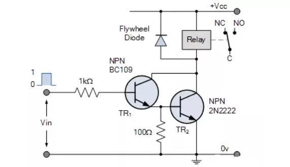
The NPN Darlington relay switch circuit employs two NPN transistors configured in a manner where the emitter current of the first transistor, TR1, serves as the base current for the second transistor, TR2. Applying a positive base current to TR1 automatically activates the switching transistor TR2.
Typically, when using two separate transistors in a Darlington pair, a small resistor (ranging from 100 to 1,000Ω) is inserted between the base and emitter of the primary switching transistor TR2 to ensure complete deactivation. Additionally, a freewheeling diode is incorporated to safeguard TR2 from any back electromotive force generated during the de-energization of the relay coil.
- Transistor Relay Drive Circuit
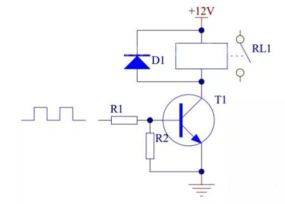
In relay drive circuits utilizing transistors, NPN transistors are the recommended choice. The circuit functions as follows:
- When the input signal is high, transistor T1 saturates and turns on, energizing the relay coil, thus closing the contact.
- Conversely, when the input signal goes low, transistor T1 cuts off, de-energizing the relay coil, resulting in an open contact.
Each component in the circuit has its specific role:
- Transistor T1 serves as the control switch.
- Resistor R1 primarily acts as a current limiter, reducing the power consumption of transistor T1.
- Resistor R2 ensures reliable deactivation of transistor T1.
- Diode D1, acting as a freewheeling diode, provides a bleeder path for the relay coil when the transistor transitions from the on state to off. This clamps the voltage across the coil to +12V.
- Optocoupler Drive Relay Circuit

The optocoupler drive relay circuit operates as follows:
- If 1U1-1 pin is connected to either 12V or 5V, 1U1 is in an active state, which results in 1Q1 also being active. When 1Q1-3 reaches 0V, the voltage across the coil is 11.7V.
- If pin 1U1-1 is unconnected or grounded, 1U1 becomes non-conductive, causing 1Q1 to deactivate. Consequently, 1Q1-3 registers 11.9V, and the voltage across the coil drops to 0V.
In summary, the world of relay switch circuits offers a multitude of designs, with transistors and MOSFETs emerging as favored choices for their fast DC switching capabilities. These versatile components enable effective control over relay coils from diverse input sources, making them indispensable for various small-scale electronic projects.”